Search results
Query: turn
Links: 167 | Categories: 2
-
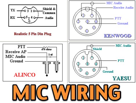 11 most popular MIC wiring diagrams including AZDEN Alinco Icom Kenwood Yaesu Astatic Cobra Sadelta Turner microphens diagrams and pin-end views
 -
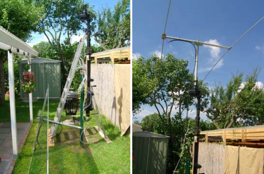
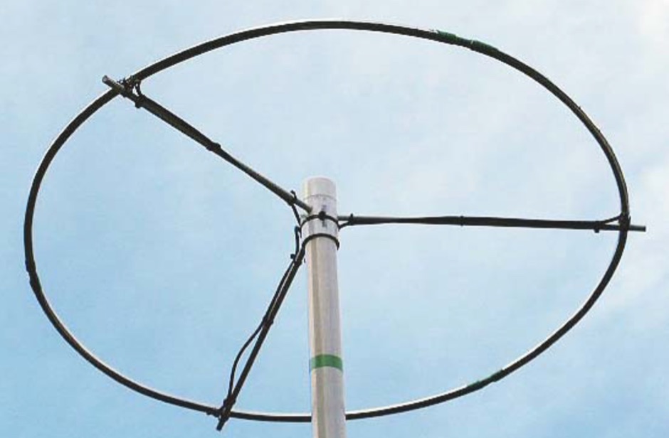
 The 160/80m coaxial receiving loop antennas are designed to enhance reception on the top bands while minimizing noise. These antennas are particularly beneficial for operators with limited space, as they can be constructed using lightweight materials, making them portable and easy to deploy. The standalone 80m loop has a diameter of approximately four feet, allowing for easy rotation and installation above existing VHF antennas. Over the years, many amateur radio operators have turned to loop antennas as a viable alternative to traditional beverage antennas. The design allows for significant noise reduction, especially when paired with a quality pre-amplifier. Experimentation with various configurations has led to the discovery that diamond-shaped loops provide optimal performance. Users have reported a noticeable improvement in signal quality, making these loops a valuable addition to any low-band DXing setup.
 -
 Demonstrates the construction of **magnetic loop antennas**, detailing both multi-turn and single-turn designs. It covers a 30-inch diameter multi-turn loop for 80 meters, based on a February 1996 QST article, and an octagon single-turn loop made from 15mm copper tube with a 4.8-meter circumference, operating from 7 MHz to 14 MHz. The document also presents a smaller 800mm diameter loop for 14 MHz to 28 MHz, emphasizing the importance of high-voltage tuning capacitors. Covers the design and construction of custom **butterfly capacitors** and piston capacitors, including a split stator capacitor with 140 pF capacitance and a 6000 Volt rating, and a butterfly capacitor with 5-65 pF and 7200 Volt rating. It explains why butterfly capacitors are preferred over split stator types for high power applications due to lower losses and direct series connection of rotors, reducing resistive losses from wiper contacts. Material recommendations include clear PVC for plates and brass or stainless steel for non-magnetic hardware. Addresses practical considerations such as feeding the loop with a shielded 1/5 Faraday loop made from RG213 or RG8 coax, achieving VSWR 1.1 across bands, and optimizing its placement 180° from the capacitor. It also discusses mechanical joint resistance, dissimilar metal oxidation prevention using Vaseline, and a simple method for determining radiation angle with a TL-light tube. The guide includes diagrams for rotor, stator, and end plate construction.
 -
 GM4JMU shortened dipole for 40 meters band. This article illustrates in detail how to build a resonant antenna for 7.030 MHz. Cut two 10.25-meter pieces of insulated wire, wind 40 turns of wire onto plastic tubing, and connect the wire to a central insulator using a choke balun built of RG174AU coax and a ferrite toroid. Once built, the antenna is adjusted by altering the wire length to produce the lowest Standing Wave Ratio (SWR) for best performance. The guide emphasizes careful building and adjustment for the best results.
 -
 G5RV 40m Beam Antenna. Adding a 28 ft. piece of vertical wire to one end of a 102 ft. center-fed dipole turns it into a 40m beam with a very wide beamwidth
 -
 Monitoring shortwave broadcast stations effectively requires accurate schedule information to identify transmissions. This online utility offers a straightforward, graphical interface designed to search for and display current shortwave radio broadcasting schedules. Users can precisely filter results by frequency, specific language, broadcaster, time of day, and even by shortwave band, which simplifies the process of pinpointing desired content. The database, last updated on March 26, 2023, details station callsigns (e.g., BBC), start and end times in UTC, days of the week, broadcast language, transmitter power in kilowatts, and azimuth. Crucially, it includes the precise geographical coordinates of transmitter sites, such as Woofferton in the UK or Al Seela in Oman. This data is invaluable for predicting signal paths and optimizing antenna direction for improved reception, a key consideration for serious SWLs. For instance, a search for BBC English broadcasts at 21:04 GMT quickly reveals multiple active frequencies like 17780 kHz from Woofferton, offering a clear overview of current transmissions. The tool processes queries rapidly, returning results within seconds, demonstrating its efficiency for broadcast listening enthusiasts seeking timely information.
 -
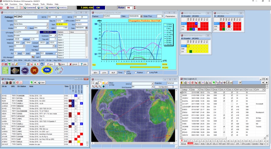 Swisslog, a robust freeware logging program, integrates seamlessly with various external devices and online services, making it a central hub for station operations. My field experience with similar logging software confirms the critical importance of features like real-time logging to services such as eQSL, QRZ, and Club Log, which Swisslog supports with both upload and download synchronization. The program also offers comprehensive award tracking for approximately 150 built-in awards, with the flexibility to add more, alongside detailed statistical reports. Beyond basic logging, Swisslog provides advanced functionalities like direct interfacing with popular digital mode software including WSJT-X, JTDX, and FLDIGI, ensuring accurate and rapid QSO entry for FT8 and other modes. It also supports multiple transceiver control (up to 8) from major manufacturers like Yaesu, Kenwood, and ICOM, and integrates with rotor control systems such as ARS-USB and Hy-Gain DCU. The _DX-Cluster_ integration is particularly useful, displaying spots with real-time award status and automatic detection for SOTA, POTA, and WFF from spot comments, which can significantly improve DXing efficiency. The software's world map feature includes various projections and layers for DXCC, IOTA, and WAZ, with a **double-clicking** function to turn the rotor, and provides accurate propagation predictions. It also supports multiple callbook and QSL manager databases, including QRZ and HamCall, and offers _multilanguage_ support in English, French, German, Italian, Portuguese, and Spanish.
 -
 Presents a practical design for a **crossed-dipole turnstile antenna** specifically engineered for 2-meter Amateur Radio Direction Finding (ARDF) events. The author, WB6RDV, details a robust, omnidirectional, horizontally-polarized antenna, addressing the international ARDF rules requiring such characteristics at a height of two to three meters above ground. This contrasts with the vertical polarization often used in Southern California, highlighting the design's adherence to specific event requirements. The electrical design employs a classic crossed-dipole with a 75-ohm phasing section, resulting in a slight impedance mismatch and an SWR of approximately 1.3:1 with a 50-ohm feedline. Construction utilizes readily available and inexpensive PVC plumbing components and 1/8-inch bronze welding rod for elements. The guide provides step-by-step instructions for mechanical assembly, including drilling element holes at precise 90-degree spacing and preparing the RG-179 matching section. WB6RDV shares insights from his own build experience, discussing the use of plated brass versus aluminum spacers for element attachment and the effectiveness of crimping as an alternative to soldering. The document also covers final assembly, including the integration of ferrite beads as a choke balun and options for weatherproofing and alternative mounting configurations, emphasizing the adaptability of the design for other VHF bands through scaling.
 -
 SigJenny turns your PC into a flexible and powerful audio signal generator for free. It can create multiple waveforms, sweep, fire single or repeating tone bursts. You can save your sound as a wav file, display a frequency response, use SigJenny a bit like an oscilloscope, and do a very good impression of a police car!
 -
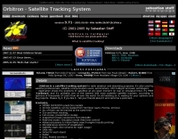 Orbitron, a cardware application, provides robust satellite tracking capabilities for radio amateurs and visual observers alike. It leverages NORAD SGP4/SDP4 prediction models to accurately display satellite positions in real-time or simulation, accommodating up to 20,000 objects loaded from _TLE files_. The software includes an advanced search engine for satellite passes and _Iridium flares_, offering printable results for planning observations or QSO attempts. Sebastian Stoff's creation supports various visualization options, including a 'Nightlife' dark color scheme for nocturnal use, and integrates a database of cities and satellite frequencies. Users can synchronize their PC clock via NTP and update TLE data over HTTP, with ZIP support. The application also features rotor and radio control capabilities, either built-in or through user-defined drivers, which is particularly useful for automating antenna pointing during satellite passes. Its interface is designed for ease of use, making satellite tracking accessible even for beginners. First released in 2005, Orbitron 3.71 runs on Windows 9x/Me/2k/XP/2k3/Vista and can operate on Linux via _Wine emulation_, requiring minimal system resources. The software's precision relies on periodic TLE updates, especially for low-Earth orbit objects, to account for orbital decay and maneuvers by satellites like the ISS or Soyuz.
 -
 This Test Tone Generator (TTG) turns your PC into a function generator and enables you to demonstrate, test and tune sound systems, create sound effects and a whole range of other uses to suit your needs. It can also be used for educational purposes.
 -
 This drawing shows a simple 10 meter wire J-pole antenna designed for 28.4 MHz. It is a vertical, end-fed Zepp-style antenna made from common materials and intended for easy home construction. The main radiating element is a straight length of stranded copper wire, either 14 or 18 gauge, cut to about 16.5 feet. At the top, the wire is supported by an insulator, allowing the antenna to be hoisted vertically. The matching section is made from 450-ohm ladder line, approximately 7 feet 9.5 inches long, and shorted at the bottom. This matching stub transforms the impedance so the antenna can be fed with coaxial cable. The feed point is tapped about 6 inches above the bottom of the stub, with the shield and center conductor connected at the proper points. A choke balun is formed with five turns of RG-58 coax in a 4-inch diameter loop to help reduce unwanted RF on the feed line. The drawing notes that this antenna has about 0 dBd gain, similar to a dipole, but offers an omnidirectional pattern and low-angle radiation when installed high. Its main advantage is practical performance, simple construction, and effective coverage for 10 meter operation.
 -
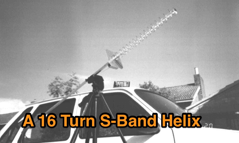 This design represents the smallest practical antenna for Oscar-13 mode-S. Perfect beacon reception at all times is possible, and acceptable SSB even at 43,000 km range.
 -
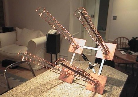 A homebrew project of a quadruple helix antenna system based on G3RUH 16 turn helix antenna for 2.4 GHz.
 -
 Demonstrates the construction and performance of an updated ZS6BKW multiband dipole, a variant of the _G5RV_ antenna, specifically designed for HF operation. The article details a real-world installation using 13.5m copper wire elements and 12.2m of 450 Ohm ladder line, configured as a sloping inverted-V with the apex at 10m and ends at 4m above ground. It covers the critical aspect of impedance matching, incorporating an 8-turn choke balun at the feedline transition to RG-58U coax to mitigate RF common mode current. Measurements confirm favorable SWR readings below **1.3:1** on 7.1 MHz, 14.11 MHz, 18.06 MHz, and 24.8 MHz, indicating effective resonance across 40m, 20m, 17m, and 12m bands. The installation also shows usable SWR dips on 3.55 MHz (5:1), 29.02 MHz (2:1), and 50.84 MHz (3:1), extending its utility to 80m, 10m, and 6m with an antenna tuning unit. Initial on-air results report clear reception of stations over **5000km** away, validating its DX potential.
 -
 Choose Iron Powder or Ferrite and calculate required turns
 -
 Turn your android mobile phone or tablet into an affordable and portable software defined radio scanner
 -
 A rotary trapped-dipole for 17 and 20 meters, as described by IZ7ATH, presents a practical solution for multi-band HF operation. The author, Talino, recounts his experience building this antenna for IK7ZCQ, detailing the evolution from an initial concept involving a grounded-driven element and gamma-match to a direct-fed, non-grounded design. His pragmatic approach, adapting available materials, is evident throughout the construction narrative, particularly with the use of eight tapered aluminum pipes for the driven element. Construction specifics include precise measurements for the aluminum tubing, with diameters ranging from 30 mm down to 16 mm, and a critical note on reducing tip thickness for weight optimization. The _traps_, initially a concern, are fabricated using 8 turns of RG58 coax on a 27 mm support, tuned to resonate at 18.1 MHz using a dip-meter. Talino emphasizes sealing the traps with RF glue and PVC tape to prevent water ingress, a crucial step for longevity. Field test results, conducted on a 10-meter pole in a clear garden environment, showed an SWR of 1.2:1 on 17 meters and 1.5:1 at 14.200 MHz. While SWR varied slightly when installed at Mario's QTH due to nearby objects, the antenna's performance remained commendable. The final half-dipole length is 46 cm for the 18 MHz tips, and the total weight is under 6 kg, with potential for further reduction.
 -
 Tarheel Antennas presents its product line of motorized **screwdriver antennas** and stainless steel mounting solutions, engineered for both amateur radio operators and commercial users. The resource details the manufacturing process, emphasizing in-house CNC machining and the use of quality materials for durability and performance. It highlights the company's commitment to U.S.-based manufacturing, with products built in St. Joseph, MO, since 2008. The site provides essential contact information for sales and technical support, including email addresses and phone numbers. It also includes a mailing address for physical correspondence. While noting a temporary absence from the Dayton Hamvention in 2024, the company expresses intent to return in 2026, indicating engagement with the amateur radio community.
 -
 A 2-meter Turnstile antenna, detailed for amateur satellite communication, offers a straightforward build for those looking to engage with orbiting transponders. The author, WB8ERJ, shares his personal design and construction methods, emphasizing the antenna's simplicity and effectiveness for LEO (Low Earth Orbit) satellite work. This design provides a circularly polarized signal, crucial for mitigating _Faraday rotation_ and signal fading often encountered with linearly polarized antennas when tracking satellites. Construction involves readily available materials like PVC pipe and copper wire, making it an accessible project for many hams. The article includes practical advice on element spacing and feed point considerations, drawing from the author's hands-on experience in the shack and field. It highlights the antenna's utility for receiving signals from various amateur satellites, including the popular AO-91 and AO-92. The Turnstile's inherent omnidirectional pattern in the horizontal plane, combined with its circular polarization, yields consistent signal reception, often resulting in **stronger decodes** and **more reliable contacts** compared to basic dipoles or verticals.
 -
 This is a hex beam designed for six meters. It has three elements with a turning radius of 54 inches. This antenna can be built from low cost materials available from the local hardware store. By WB3BEL
 -
 A 40-meter reversible _Moxon rectangle_ antenna project details its construction and performance, featuring 51-foot long sides and 7.7-foot turned-in sections. The design incorporates a 16.5-foot boom, with elements spaced 1.1 feet apart, constructed from #14 covered wire. It utilizes two double-pole relays for switching between NE and SW directions, achieving F/B ratios up to 40 dB on CW and 30 dB on SSB, with distinct reflector stub settings for each mode. This antenna replaced a full-size 2-element Yagi, demonstrating comparable forward gain while offering superior F/B ratios and directional flexibility. _EZNEC_ modeling indicates only 0.2 dB less forward gain than the Yagi. The system uses no baluns, relying on half-wave feedlines and switched stubs for impedance matching. The antenna is tree-supported at 45 feet, with its effective radiation height modeled at 80 feet due to local terrain, enhancing its performance over a nearby lake.
 -
 Constructing an HF End-Fed Half-Wave (EFHW) vertical antenna, the resource details the winding of a monoband matching unit, inspired by _AA5TB_, designed to provide a 50 Ohm impedance match without a ground plane or antenna tuner. It specifies the use of a _T200-2_ ferrite core for the transformer, outlining the 13-turn secondary and 2-turn primary winding process with enamelled copper wire. The document also describes the integration of a coax capacitor, whose length is critical for tuning and varies by band, with specific starting lengths provided for 20m, 17m, 15m, 12m, and 10m operation. The practical application section guides the builder through tuning the antenna using an antenna analyzer, emphasizing the iterative process of spacing secondary windings and trimming the coax capacitor to achieve resonance at the desired band frequency. It highlights the antenna's low angle of radiation, beneficial for DX, and claims up to 2 S-points improvement over a _G5RV_ or similar doublet when used as an omnidirectional vertical. A comprehensive shopping list, including specific part numbers from _Rapid Electronics_, is provided, along with advice on selecting fiberglass fishing poles for support and suitable antenna wire.
 -
 Here are construction plans of a Turnstile antenna that can be used for space communication on the 2 meter amateur radio band. Specifically for 145.80 mHz
 -
 This is a base-loaded vertical antenna that mounts on the car's roof. The loading coil is designed as a variable inductor, with a three-legged chariot that travels up and down inside the coil, with grooved brass wheels running on the coil turns, and driven by a slotted rotor tube.
 -
 The Buddipole website showcases a range of portable amateur radio antenna systems, including the **Buddipole**, Mini-Buddipole, Buddistick PRO, and BuddiHEX, designed for rapid deployment and multi-band operation from 40 meters to 2 meters. Each product page details specifications, operational modes (dipole or vertical), and compatible accessories like tripods, masts, and baluns. The site also features portable DC power management systems such as the PowerMini 2 and PowerPlus, which include integrated battery chargers and solar controllers, catering to off-grid or field day setups. Instructional videos demonstrate antenna assembly, tuning, and deployment techniques for various configurations, including the VersaTee vertical and Mini-Buddipole. Customer testimonials and DXpedition highlights, such as operations from Montserrat (VP2M) and Dominica (J38), provide real-world examples of the equipment's performance in challenging environments. The company, established in 2001, emphasizes modularity, versatility, and efficiency in its product line, all manufactured in the USA. Shipping information, a 30-day return policy with no restocking fee, and contact details for their Heber City, Utah facility are clearly presented. The site serves as a direct sales portal, offering a comprehensive catalog of antennas, power solutions, and components for portable amateur radio enthusiasts.
 -
 For amateur radio operators seeking to confirm two-way radio contacts, a QSL card serves as a traditional, tangible verification. ON5UR QSL Printing provides a service for designing and printing high-quality, full-color QSL cards, including options for full-color backsides. The service offers various paper weights, such as 250, 280, 300, and 400 grams, allowing hams to select a card stock that meets their preferences for durability and feel. Pricing structures are detailed for different quantities, with 1000 cards starting at 96.00 Euro for 300-gram stock with gloss laminate, inclusive of design costs. The service includes free QSL cards with larger orders, such as 500 free cards with a 2000-card order, or 500 free cards with a 7000-card order. Shipping costs are categorized into six zones, primarily covering Europe, with specific pricing for countries like Belgium (Zone 1) and a request-based system for other regions and export conditions outside Europe. Testimonials from operators like M0URX highlight the design quality and quick turnaround, which are crucial for DXpedition QSL managers needing efficient processing.
 -
 The 40/60/80 is a portable loop that covers 80 meters with a high degree of compromise
 -
 Modifying the _ICOM IC-706MKII_ transceiver for out-of-band transmit capability involves specific surface-mount device (SMD) removal on the main circuit board. This procedure enables transmit functionality from 0.5 MHz to 200 MHz, excluding the commercial FM-Wide broadcast band, significantly expanding the radio's operational frequency range. The modification requires careful handling of small components and a fine-tipped, low-wattage soldering iron. Prior to beginning, all programmed memories and initial setup configurations must be noted, as the modification process will erase them. The instructions detail the necessary tools, preparation steps, and the precise location of the two SMD diodes to be removed. These diodes are situated near an oblong crystal can and a test point labeled _CP3_ on the main board. Successful completion returns the unit to its default configuration, necessitating manual reprogramming of memory channels and initial settings. This project is suitable for operators with experience in SMD work and fine soldering.
 -
 Horizontal HF 6-Band turning arranging emitter with 2 elements Maria Maluca
 -
 An homemade portable vertical antenna with a trap near the mid point of the main element. The trap is made with 42mm diameter PVC pipe with 9 turns of wire on it
 -
 Constructing a compact, two-band magnetic loop antenna for HF operation, especially from constrained locations like a balcony, presents unique challenges. OK1FOU's design, inspired by DJ3RW's 50 MHz loop, addresses these by employing an unusual side-fed configuration and placing the symmetric, two-section variable tuning capacitor at the bottom of the loop, directly connected to the coax shield. The article provides specific material recommendations, including two 1-meter wooden pales and about 3 meters of thick loudspeaker cable, noting the high current (60A at 100W) in the loop. Construction steps detail forming two turns with a 5 cm gap, using a GDO to pre-tune the open loop to a frequency slightly above the desired highest band, and then integrating the tuning and coupling capacitors. For 10/14 MHz, an open loop resonance of 16-17 MHz is suggested. Practical experience with the 10 MHz band from a third-floor balcony in Prague (JO70GC) shows a 1:1 SWR across most of the band without an external ATU. While DX traffic was modest due to the urban environment, QSO examples with RA6WF, LA6GIA, G0NXA, and LZ1QK on 10 MHz are provided, demonstrating its operational capability.
 -
 The W1TAG LF Receiving Loop is a specialized antenna project for LF reception, designed to mitigate local noise and enhance weak signal pickup on the lower frequencies. This square loop, measuring 6 feet per side, utilizes 14 turns of #12 THHN wire wound on a PVC frame, offering a robust mechanical structure. The design incorporates a series-tuned circuit with a coupling transformer, allowing for tuning from over 400 kHz down to _45 kHz_ using a switched capacitor bank. Construction details include the use of 1.5-inch PVC pipe for the frame, with specific measurements for spreaders and drilled holes for wire threading. The two 7-turn sections of wire are connected at the center, providing an option for a center tap. The loop rotates on a 1-inch steel pipe, enabling directional nulling of noise sources. The tuning unit, housed in a box clamped to the PVC, employs a 1:2 step-up transformer wound on an _FT-82-77 core_ and uses relays to switch capacitance values from 50 pF to 6400 pF, providing precise frequency adjustment. The current setup connects to the shack via 100 feet of RG-58, feeding into a W1VD-designed preamp, with plans for a balanced, shielded twisted pair cable upgrade.
 -
 AEA Wireless Director Software Series turns PC's (running Windows 95/98/2000/ME or NT) into powerful tools that expand the use and power of SWR, Return Loss and Complex Impedance Analyzers.
 -
 A popular 2 meter antenna returns in an improved, easier to reproduce form, 2008 QST article
 -
 Demonstrates the essential steps for winding **toroidal cores**, a fundamental skill for amateur radio operators engaged in homebrewing and kit building. It addresses the critical aspects of selecting the correct core material and wire gauge, emphasizing the importance of precise turn counting and consistent winding tension to ensure optimal circuit performance. The resource details methods for preparing the wire, including techniques for safely removing enamel insulation from leads using flame, sandpaper, or a solder pot, and provides guidance on tinning the exposed wire. Explains the process of mounting the wound toroid onto a printed circuit board, highlighting the need for careful lead placement and secure soldering to prevent shorts and ensure mechanical stability. It also offers a practical formula for calculating the required wire length based on the desired number of turns and the specific **toroid** size, referencing common core types like T-50 and FT-240. The guide stresses the importance of verifying the inductance of the wound component, often using an inductance meter, to confirm it matches design specifications. Provides practical tips for handling multi-filar windings and managing short lead lengths, which can be particularly challenging. It underscores the necessity of meticulous attention to detail throughout the winding and installation process to achieve reliable and efficient RF circuits.
 -
 The QRP choke balun described utilizes a high permeability ferrite rod and RG-174 coax, aiming to present high impedance to common-mode currents across the HF spectrum. The construction involves winding as many turns of RG-174 as possible around the ferrite rod, then encapsulating the assembly with hot glue. This design prioritizes maximizing inductance to suppress unwanted shield currents, particularly in unbalanced antenna configurations. While the balun's effectiveness is subjectively reported as good, a potential design consideration involves the dielectric properties of the hot glue. This material could increase turn-to-turn capacitance, potentially reducing the balun's performance at higher HF frequencies, though this specific aspect has not been formally tested by the author, _AA5TB_. The project serves as an illustrative example of a practical, junk-box construction rather than a rigorously engineered solution. Photographs detail the evolution of the balun, from the initial winding process to its integration within a _B&W dipole center insulator_ and final camouflaged assembly.
 -
 Operating a ZS6BKW antenna often involves understanding its lineage from the _G5RV_ design, with specific modifications by ZS6BKW to optimize performance on several bands. Through computational analysis and field measurements, the antenna's dimensions were refined to allow operation on 10, 12, 17, 20, and 40 meters without an antenna tuner. For 80, 30, and 15 meters, a tuner is necessary, though efficiency on 30 and 15 meters is noted as not particularly high. The physical configuration consists of two 13.755-meter radiating elements fed by a 12.20-meter section of 450-ohm ladder line. Tuning the antenna on the 20-meter band is critical, and any deviation in the ladder line's characteristic impedance necessitates recalculating the element lengths. The design is also referenced in the 12th edition of _Rothammel's Antennenbuch_, page 219. Proper common mode current suppression is crucial at the transition from ladder line to coaxial cable. This can be achieved with a common mode choke, such as several turns of coax wound into a coil or over a ferrite toroid like an Amidon T130. While a 1:1 balun is an option, it may introduce issues.
 -
 Demonstrates the design and construction of a 9-element Yagi antenna for the **70 cm band** (432 MHz), based on the DK7ZB concept. The resource details EZNEC+ calculations for a single antenna, providing gain, sidelobe suppression, and front-to-back ratio figures. It also presents a comprehensive analysis of stacking two such antennas, including optimal stacking distance (1000 mm) and the resulting performance enhancements for the stacked array, such as an increased gain of 17.03 dBi. The article includes detailed drawings, wire file dimensions in millimeters, and azimuth/elevation plots for both single and stacked configurations. Practical construction steps are documented with original photographs, illustrating element mounting, the **28 Ohm matching system** using two quarter-wave 75 Ohm transmission lines, and the critical N-connector wiring. It also covers the iterative process of fine-tuning the driven element length to achieve a return loss of 20 dB, validating the EZNEC+ simulation results with actual measurements.
 -

-
 The page discusses Axial-Mode Helical Antennas, focusing on turning helical antennas over perfect ground and modeling helices in NEC-2 for optimized design. It covers topics such as high-gain performance, broadband, impedance matching, radiation pattern, feedline, balun, near field, far field, and DIY applications.
 -
 Demonstrates the construction and measurement of a single-turn HF receiving loop antenna, built from common materials like electrical conduit and lamp cord. The resource details the physical dimensions, including a 4-meter circumference, and calculates the theoretical inductance at approximately _6.4 uH_. It outlines a method for determining resonant frequencies across the 4-17 MHz range using a _C Jig_ and a _VR-500 receiver_, coupling the loop with a ferrite ring. The article also discusses the impact of receiver coupling on the loop's Q factor, noting a degradation in sharpness due to the transformer's reflected impedance. Analyzes the observed resonant frequency patterns, highlighting an unexpected rise in the loop's effective inductance at higher frequencies, particularly above 13 MHz. While some increase is attributed to distributed capacitance, the rate of rise suggests further investigation. The experimental setup provides practical insights into the challenges of maintaining high Q in simple receiving loops and offers a comparative reference for other homebrew antenna projects, such as those by _VK2TPM_.
 -
 The Kenwood TS-950S and TS-950SD HF transceivers are fine radios. However, many, if not all, of them were produced with a design flaw which allows the RG GAIN control to cease function in the presence of a strong signal IF the AGC has been turned OFF
 -
 A 500-watt mobile antenna project details the conversion of an old 10m hamstick into a highly efficient, multiband "bugstick" for HF operation. The core modification involves replacing the original coil with 25 turns of 6 turns-per-inch, 1.5-inch diameter coil stock, fabricated from #14 wire. This design, intended for a 3-magnet mount on a vehicle cab, achieves resonance on multiple bands by shorting out specific turns on the coil, similar to a **bugcatcher** antenna. Measurements taken with an MFJ-259 analyzer on a GMC pickup show 0 turns shorted for 20 meters (14.2 MHz), 10 turns for 17 meters, 16 turns for 15 meters, 19 turns for 12 meters, and 23 turns for 10 meters. The construction emphasizes using UV-resistant tie-wraps and #14 solid wire with crimp lugs for robust RF connections, bypassing the fiberglass rod for current flow. A bonus section details a 40-meter version, utilizing 48 turns of 8 TPI, 2-inch diameter coil stock.
 -
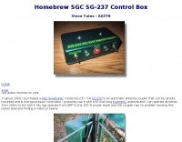 A remote control box for the SG-237 that allow to turn on and off, check status the SGC tuner remotely by AA5TB
 -
 A homemade VHF/UHF vertical antenna made essentially with RG58 coax cable, with a 9 turns choke balun to prevent the shield acting as a RF Radiator.
 -
 The Peaberry SDR is the first and only do-it-yourself transceiver that doesn't require adding sound cards to your computer.
 -
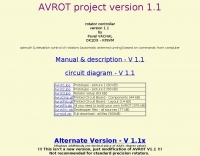 Rotator controller, azimuth & elevation control of rotators (automatic antenna turning) based on commands from computer. A project by Pavel VACHAL and OK1DX - KF9VM
 -
 The Resonant Feedline Dipole (RFD) HF antenna design utilizes a single piece of coaxial cable and a stranded wire section, forming a 1/4-wavelength radiator. This configuration, based on a 1997 ARRL Handbook design (page 20.17), functions by RF traveling on the inside of the coax shield and returning on the outside, creating the second half of the dipole. A choke wound into the feedline prevents RF current from flowing back down the feedline. Construction details include using RG-58a/u coax for a 75m version, with a 1/4-wavelength section of stranded wire soldered to the center conductor. The document provides choke dimensions for RG-213, RG-8, and RG-58 coax across 3.5 MHz to 28 MHz, specifying cable length and number of turns. Dipole dimensions are also tabulated for frequencies from 3.6 MHz to 28.4 MHz, listing overall length and individual leg lengths. Field tests included deployment near Bryson City at 5 feet off the ground and as a sloper during WCARS Field Day in Asheville, yielding successful local and regional contacts.
 -
 In this article, the author discusses the importance of good transformers for Beverages, especially for common-mode isolation. The author recommends #43 ferrite for the transformer, and provides the turns required for different core types. The author also recommends using lower permeability ferrites for better performance at lower frequencies.