Search results
Query: vor antenna
Links: 31 | Categories: 0
-
 How High should my Dipole be? Dipole Antennas and the effect of height above ground. The effectiveness of a dipole antenna is influenced by its height above ground, determined by the intended use such as DX work, local communication, directionality, omni-directionality, and feed point impedance. Through EZNEC modeling, the study evaluates a 40-meter dipole's performance at various heights, from 7 to 560 feet. Findings reveal that lower heights enhance omni-directional local communication, while higher placements favor DX work with low-angle radiation. The study emphasizes the importance of defining operational goals to optimize dipole height and performance.
 -
 This article describes how to make a quadrifilar helix (QFH) antenna easily, from inexpensive materials: uPVC plumbing pipe and RG-58U co-axial cable. A low-cost, easy-to-build Quadrifilar Helix (QFH) antenna for weather satellite reception using uPVC plumbing pipe and RG-58U coaxial cable. Unlike traditional designs requiring copper pipe and plumbing skills, this approach enables construction with basic tools and minimal technical expertise. The antenna's shorter, wider proportions favor higher elevation angles, reducing interference from horizon-level pager transmitters. Electrical connections are simplified at the antenna's apex, with the coaxial cable forming the radiating elements. Testing demonstrated consistent signal strength throughout satellite passes, proving effective weather satellite reception is achievable without precision engineering to sub-millimeter tolerances.
 -
-
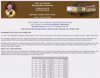
 Demonstrates the construction and performance of an updated ZS6BKW multiband dipole, a variant of the _G5RV_ antenna, specifically designed for HF operation. The article details a real-world installation using 13.5m copper wire elements and 12.2m of 450 Ohm ladder line, configured as a sloping inverted-V with the apex at 10m and ends at 4m above ground. It covers the critical aspect of impedance matching, incorporating an 8-turn choke balun at the feedline transition to RG-58U coax to mitigate RF common mode current. Measurements confirm favorable SWR readings below **1.3:1** on 7.1 MHz, 14.11 MHz, 18.06 MHz, and 24.8 MHz, indicating effective resonance across 40m, 20m, 17m, and 12m bands. The installation also shows usable SWR dips on 3.55 MHz (5:1), 29.02 MHz (2:1), and 50.84 MHz (3:1), extending its utility to 80m, 10m, and 6m with an antenna tuning unit. Initial on-air results report clear reception of stations over **5000km** away, validating its DX potential.
 -
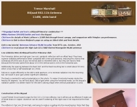
 802.11b WLAN Waveguide Antennas Unidirectional & Omnidirectional. High gain, Simple construction by Trevor Marshall
 -
 F6EZX presents a detailed account of constructing a compact, multi-band _Levy antenna_ for portable holiday operations, specifically addressing issues with local QRM from a previous _Deltaloop_ setup. The article outlines the design criteria, including multi-band operation on 40m, 30m, 17m, 15m, 12m, and 10m, a symmetrical configuration to reduce interference, and a low take-off angle for DX. Construction involves 2x 10.3m radiating elements and a 15.3m open-wire feeder (ladder line) with 7cm spacing, made from 1.5mm2 copper wire and foam pipe insulation spacers. Theoretical calculations, referencing F9HJ's "_Les antennes Levy_" book, guide the determination of element lengths and feeder impedance characteristics, aiming for a good match across bands with a commercial antenna tuner. Initial field tests with the _VCI Vectronics VC300DLP_ tuner showed a 1:1 SWR from 80m to 10m, with some difficulty on 17m. The antenna, mounted as a 45-degree slopper with the high point at 12m, successfully facilitated DX contacts to South America, particularly Chile and Argentina, suggesting a lower take-off angle compared to the previous Deltaloop which favored Brazil. The Levy antenna significantly reduced TVI/RFI, attributed to its improved symmetry and greater distance from the QRA. While signal reports on 15m and 20m were 1-2 S-points lower than the Deltaloop, its performance on 40m and 30m was comparable, fulfilling the design goals for a portable, low-cost, multi-band solution.
 -
 The W3DZZ trap dipole is a versatile and economical antenna option for amateur radio operators looking to work multiple bands without the need for extensive equipment. This antenna design utilizes traps to allow operation on various HF bands, making it suitable for both casual operators and serious DXers. Its construction is straightforward, making it accessible for beginners while still providing excellent performance for seasoned hams. Constructed with readily available materials, the W3DZZ trap dipole can be built to fit specific band requirements, allowing operators to optimize their setup for the frequencies they intend to use. The design is particularly favored for its ability to maintain a low profile while delivering effective radiation patterns. Whether you're contesting or chasing DX, this antenna can enhance your station's capabilities without breaking the bank.
 -
 A delta loop antenna project for the 40 meters band, include dimensions 80 meters band, with construction details, schematic and tuning instructions
 -
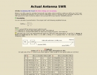 Easy for calculate formula which could be a wake-up call for you. The SWR value at the input of antenna cable is not a actual SWR of your favorite antenna.
 -
 If you are looking for an easy antenna for your favorite band, you can't go wrong with an halfwavelenght dipole, all you need is 3 insulators and some wire
 -
 Vortex Antenna Systems, radio communication antenna aanufacturer and supplier of antenna related hardware. Ham radio HF and VHF Antennas, antenna parts, mast and mounts.
 -
 A compact multiband wire antenna suitable for portable operations.
 -
 For amateur radio operators engaged in **radio direction finding** (RDF) and **transmitter hunting** (T-hunting) activities, this resource provides a catalog of printed circuit boards (PCBs) for constructing various DF and foxhunt-related projects. The offerings include PCBs for 80-meter fox transmitters and receivers, UHF fox transmitters with audio recording capabilities, and several designs for general-purpose radio direction finders. Specific projects like the "Simple 80M ATX-80 Transmitter" and the "N0GSG DSP Radio Direction Finder" are listed, along with attenuator boxes and specialized components for Doppler DF systems. The catalog details PCBs for projects published in prominent amateur radio magazines such as *73's*, *CQ*, *QST*, and *PE*, indicating their origin and design pedigree. For instance, the "Montreal Fox Controller" is sourced from the *Homing-In* column by Joe Moell, K0OV. The resource also lists components for advanced Doppler DF systems, including main boards, LED display boards, and antenna switch boards, with options for programmed PIC microcontrollers. Pricing for each PCB is provided, allowing hams to acquire the necessary components for their DIY RDF endeavors.
 -

-
 This project details the construction of a **full-sized 40-meter vertical antenna**, born from a renewed interest in 7 MHz operation and a desire for improved effectiveness over simple dipoles. The author, K5DKZ, initially focused on VHF experimentation, which provided an inventory of aluminum tubing and fiberglass spreaders for this endeavor. Before this vertical, K5DKZ utilized an 80/40 meter inverted-vee trap dipole and a 40-meter broadband dipole, but now primarily uses a pair of full-sized, phased, quarter-wave verticals spaced 35 feet apart for serious 40-meter work. The construction involves a base-heavy design for stability, using a 44.5-inch section of 1-1/4 inch steel TV mast driven into 1-3/8 inch aluminum tubing, insulated by a 105-inch section of Schedule 40 PVC pipe. The assembly reaches 31 feet, close to the 32 feet required for a quarter-wavelength on 40 meters, with fine-tuning achieved by winding wire onto a fiberglass spreader. The design is explicitly presented as a foundation for a two-element 40-meter Yagi beam, outlining modifications like substituting aluminum for steel in the base and using an inductive hairpin match for the driven element. The article also discusses tuning considerations for a large 40-meter beam, noting the 100 to 200 kHz upward frequency shift when raised, and suggesting methods for installation on a tower. The author emphasizes the cost-effectiveness and good performance of the monopole approach, especially when multiple verticals are needed.
 -
 The GM4JJJ VHF and EME pages document David's extensive work in Earth-Moon-Earth (EME) communication, specifically on the 144 MHz band, and his involvement in amateur radio astronomy. The resource details his station setup and operational experiences, providing insights into the technical challenges and rewards of bouncing signals off the moon. It offers a glimpse into the specialized equipment and techniques required for successful EME contacts, a niche but highly rewarding aspect of amateur radio. David's content shares practical applications and field results from his EME endeavors, which can be particularly useful for hams contemplating or actively pursuing moonbounce operations. The information, while not a step-by-step guide, implicitly compares the complexities of EME with more conventional VHF/UHF operations, highlighting the significant power and antenna gain necessary to overcome path losses. This resource serves as a testament to the advanced capabilities achievable in amateur radio.
 -
 Demonstrates the operational status and reception reports for the SK6RUD/SA6RR QRPP beacons, which transmit on 478.9 kHz, 1995 kHz, 10.131 MHz, and 40.673 MHz. These beacons utilize extremely low power, with the 630-meter beacon operating at approximately 0.1 watt ERP into an L-antenna, showcasing the potential for long-distance contacts under favorable propagation conditions. The site details the specific frequencies and antenna types employed, such as a vertical at 500 kHz and a 1/4 vertical for higher bands. The resource compiles over 10,530 reception reports from amateur radio operators worldwide, logging details such as date, time, band, RST signal report, locator, distance, and receiver setup. Notable long-distance reports include a 500 kHz reception by AA1A-Dave from 5832 km in 2008 and a 10.133 MHz reception by ZL2FT-Jason from 17680 km in 2010, illustrating the global reach of these low-power transmissions. Each log entry provides specific equipment used by the reporting station, including transceivers like the Yaesu FT817, ICOM IC-7300, and various antenna configurations such as coaxial mag loops, inverted Ls, and end-fed wires. The primary objective of the SK6RUD beacons is to challenge conventional notions of power requirements for effective two-way communication, proving that contacts over significant distances are achievable with minimal output. The site also includes a submission form for new reception reports, fostering community engagement and continuous data collection on propagation phenomena across different bands. The detailed logs offer practical insights into real-world propagation characteristics and the efficacy of QRPP operations.
 -
 Antenna element holders, antenna parts, aluminium tubing, fiberglass tubing, connectors and antenna mounts and hardware by Eidolon AS
 -
 Designer and manufacture of Airborne Antenna & Radomes covering a range of applications. Products include vhf antenna ,uhf antenna,navigation antenna,comm antenna,blade antenna,vor/ils antenna ,L band antenna, direction finding antenna,DF antenna,vor,ils, IFF antenna on aircraft,aircraft antenna for airborne application.
 -
 Essentially, a choke balun is designed to 'divorce' your antenna from the feed line. if your feed line is coaxial cable then you don't want it to be part of your antenna. you want to be able to deliver all your power to the radiator itself, i.e. 'the antenna'. a choke balun does this admirably
 -
 Presents a personal blog, "QSL, maraca!", maintained by Luiz Belem, PY1UR, detailing his amateur radio endeavors. The content includes posts on station setup, operating experiences, and general ham radio topics, reflecting the perspective of an active DXer and contester. The blog serves as a digital logbook and platform for sharing insights with the amateur radio community. Documents PY1UR's participation in various on-air activities, showcasing his QSL card collection and providing narratives behind specific contacts. It offers practical insights into antenna configurations and radio equipment used, demonstrating effective strategies for achieving **DX contacts** and improving station performance. The blog's entries provide a historical record of PY1UR's _amateur radio journey_.
 -
 This DIY vertical multi-band Windom antenna offers a practical and effective solution for amateur radio enthusiasts seeking a versatile and compact antenna for HF communications. Its simplicity of construction, multi-band capability, and favorable performance make it a valuable addition to any radio shack. The article provides detailed instructions on constructing the antenna and balun, along with diagrams and component specifications. Field tests demonstrated successful contacts with stations across Europe and North America on 14, 18, and 28 MHz. The antenna exhibited comparable performance to a W3DZZ dipole and outperformed a Cobweb antenna on 18 MHz. Low noise levels were observed, effectively suppressing background noise.
 -
 The Tri-pole antenna, a clever modification of a standard dipole, allows for dual-band operation by integrating a third element. This design effectively shortens the overall dipole length by 10 to 20 percent, simplifying antenna rotation and offering a compact footprint. KK4OBI's article delves into the operational principles, using a 6 and 10-meter Tri-pole as a primary example, and provides comprehensive instructions for constructing any Tri-pole antenna within the 6 to 15-meter range. Key to the Tri-pole's performance is its off-center feed, necessitating a common mode choke at the feed point for optimal tuning and reduced noise. The author outlines a methodical approach to determining element dimensions, starting with a vertical element frequency calculated as 0.47 times the sum of the desired upper and lower band frequencies. This calculation, along with K-values derived from trend lines, guides the initial lengths for the horizontal arms, demonstrating how a 10m-6m Tri-pole can achieve a total horizontal length 78% shorter than a conventional 10-meter dipole. Tuning and balancing are critical, with the article detailing adjustments to arm lengths and the vertical element to achieve balanced SWR values, as validated through 4NEC2 simulations. Radiation patterns are analyzed at various elevations, showing gains around 5.7 dBi and favorable take-off angles for DX contacts. Construction details specify aluminum tubing dimensions, U-bolts, and an SO-239 connector, emphasizing the importance of a ferrite-based choke for wideband operation.
 -
 Presents amateur radio activities and experiences from JJ0LUU and JJ0LXF, two operators based in Japan. The weblog, hosted on shinshu.fm, documents their on-air operations, equipment setups, and general ham radio interests. Content often includes details about specific contacts, antenna configurations, and local operating conditions within the Japanese amateur radio community. The resource primarily focuses on personal operating logs and occasional technical discussions relevant to their station. It offers a glimpse into the daily life and pursuits of Japanese **amateur radio** operators, detailing their engagement with various bands and modes. JJ0LUU and JJ0LXF share their passion for radio communication, contributing to the broader online repository of individual ham radio narratives. The site serves as a digital logbook and informal platform for sharing their **DXing** and contesting endeavors.
 -
 Microwaves101 provides an extensive repository of information covering fundamental principles of microwave design, targeting engineers and radio amateurs interested in the higher frequency spectrum. The site features a detailed _encyclopedia_ of microwave terms and concepts, alongside practical design considerations for various components and systems. It serves as a foundational reference for understanding RF propagation, transmission lines, and active/passive microwave circuits. The resource includes numerous calculators for impedance matching, filter design, and other critical RF parameters, facilitating hands-on project development. Discussions on **10 GHz** equipment and **24 GHz** projects highlight practical amateur radio applications, extending to operations up to 134 GHz. Content spans from basic theory to advanced topics like MMIC design and antenna characteristics, supporting both educational and practical endeavors in microwave technology.
 -
 Opting for a visually appealing inverted L configuration, G4WIF anchors the End Fed Half Wave antenna to an old clothes line pole, seeking cost-effectiveness in their endeavor. Despite initial misconceptions about transformer components, a £7.95 investment in a T240-43 toroid and DIY mounting container resolves the issue. Reflecting on commercial alternatives, G4WIF's homemade solution proves both economical and sufficient for their amateur radio needs.
 -
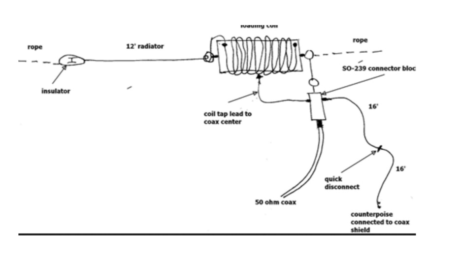
 The quarter-wave Marconi working against ground is a popular and inexpensive antenna for 160 meters. A lot of newcomers to the band favor this simple antenna because it's easy to put up, it isn't too big, and it works.
 -
 What do amateur radio operators worldwide, think of their passion? What do we wish for? What are we frustrated about? How many of us are active, versus those that are taking a break? Do we have favorite radios, antennas, or even favorite cw paddles? Do we prefer one contest over another? The best way to find out is if we all participate in Ham Census. Join in and let all amateur radio operators know your thoughts "share your views" then you can find out what everyone else is thinking, in real time. Help shape the future of ham radio by participating in the world's most complete survey of amateur radio.
 -
 This article details an Inverted-L antenna design optimized for 160-meter band operation, consisting of a 10m vertical section and a 28m horizontal section supported by Spiderpoles. Despite its relatively low height compared to the wavelength, the antenna has demonstrated impressive DX capabilities, achieving contacts up to 3,453 miles into Asiatic Russia. The system incorporates a Pi-Network ATU at the base for tuning flexibility. While modeling shows a radiation pattern favoring the South, practical operation indicates effective all-round coverage on Top Band.
 -
 VE1ZAC's analysis details the performance of **MFJ927** and **SGC239** autotuners with portable HF vertical antennas, specifically comparing 31 ft and 43 ft configurations. The resource originated from challenges encountered during a Maritime QSO Party roving operation, necessitating a lightweight and easily deployable antenna system. Target bands for the contest included 80, 40, 20, 15, and 10 meters, with a maximum power handling of 100 W CW. The author utilized a 30-foot carbon fiber push-up pole to support a vertical wire element, noting its 2 lb weight and reliability. EZNEC modeling was employed to predict performance, showing favorable results for a 30-foot vertical with elevated radials, particularly on 40 and 20 meters. Feedpoint impedance measurements, taken with an AIM4170C, are presented for various HF bands, both with and without a 41-foot RG6 stub designed to reduce reactance on 80 and 20 meters. The stub significantly improved matching on these bands, easing the tuner's workload. Operational tests revealed issues with the MFJ927's reliability during contest setup, leading to reliance on the K3's internal tuner. The SGC239, tested post-contest, performed flawlessly. A detailed side-by-side comparison covers mechanical aspects, connection options, power bias, impedance range, board quality, and documentation. Modifications to the MFJ927, including a new aluminum case, white paint for heat reduction, and upgraded impedance-measuring resistors, are also described.
 -
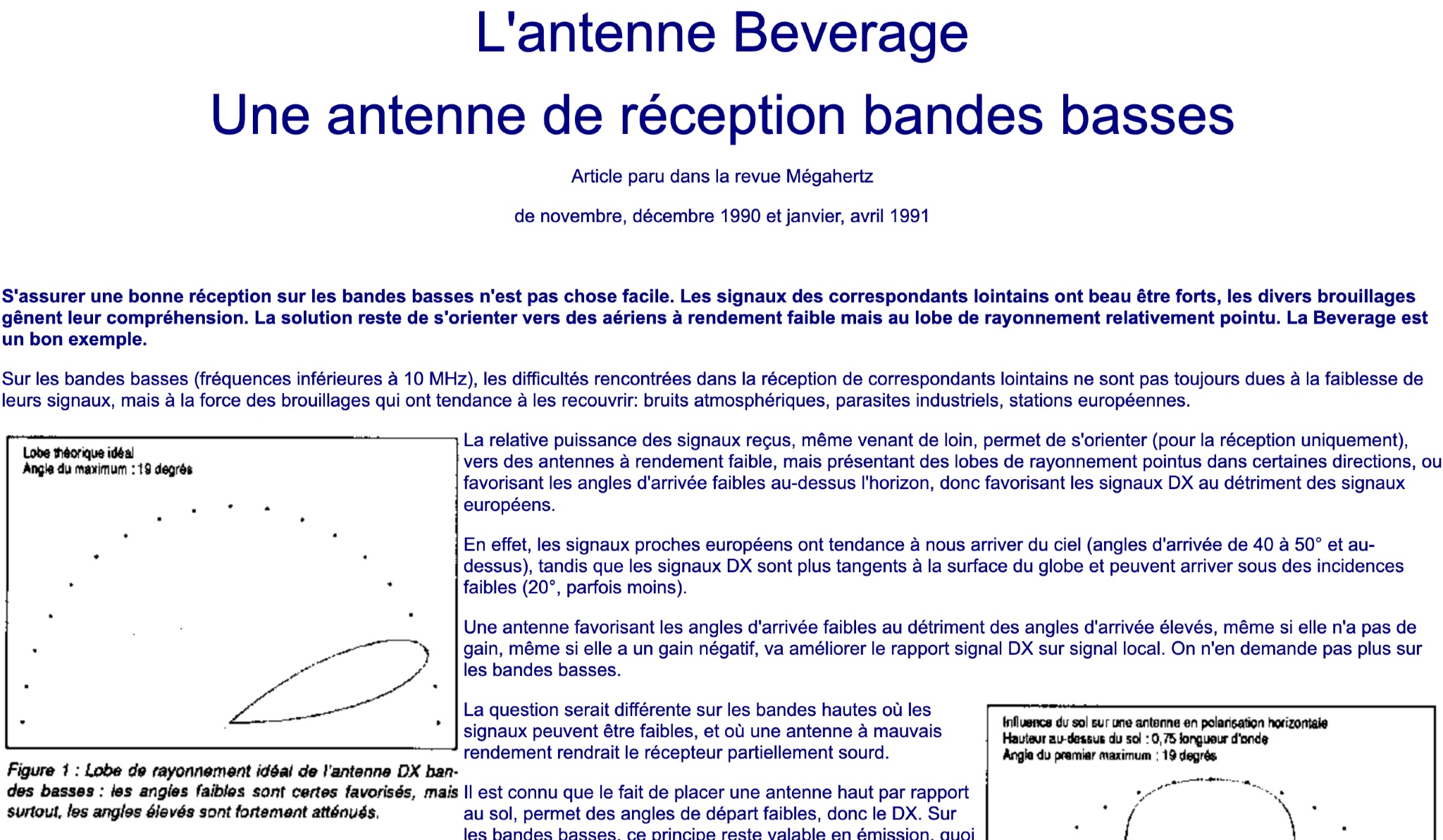 This article discusses the Beverage antenna, a reception antenna for low bands, originally published in the Megahertz magazine between November 1990 and April 1991. It explains the challenges faced in receiving signals on low bands due to interference and how the Beverage antenna's directional radiation pattern can help improve reception of distant stations. The article highlights the importance of choosing antennas with low efficiency but sharp radiation lobes for better DX signal reception. It also compares the reception characteristics of signals from European stations versus DX stations, emphasizing the benefits of antennas favoring low arrival angles for DX signals on low bands.