Search results
Query: wiring antenna
Links: 12 | Categories: 0
-
 Illustrates the specific wiring and configuration steps required to interface an SGC-230 Smartuner with an Icom IC-706 HF/VHF/UHF transceiver. The document details the necessary connections for power, control, and RF signal paths between the two devices, ensuring proper impedance matching and automatic antenna tuning functionality. It specifies the pin assignments for the IC-706's ACC socket and the SGC-230's control port, crucial for successful integration. Outlines the operational considerations for the combined system, including initial setup procedures and potential troubleshooting tips for common connectivity issues. The resource presents a clear, diagrammatic representation of the interconnections, which aids in visual comprehension of the required cable fabrication or modification. Covers the specific settings within the IC-706 menu that need adjustment to enable external tuner control, such as the 'TUNER' function and other relevant parameters. This ensures the transceiver correctly communicates with the SGC-230 for efficient antenna tuning across various amateur bands.
 -
 Some antenna manufacturers place baluns at the incorrect location in LPDA arrays, or tell you to route the cable incorrectly. This can cause substantial RFI and all sorts of weird problems like RF into house wiring.
 -
 Demonstrates the design and construction of a 9-element Yagi antenna for the **70 cm band** (432 MHz), based on the DK7ZB concept. The resource details EZNEC+ calculations for a single antenna, providing gain, sidelobe suppression, and front-to-back ratio figures. It also presents a comprehensive analysis of stacking two such antennas, including optimal stacking distance (1000 mm) and the resulting performance enhancements for the stacked array, such as an increased gain of 17.03 dBi. The article includes detailed drawings, wire file dimensions in millimeters, and azimuth/elevation plots for both single and stacked configurations. Practical construction steps are documented with original photographs, illustrating element mounting, the **28 Ohm matching system** using two quarter-wave 75 Ohm transmission lines, and the critical N-connector wiring. It also covers the iterative process of fine-tuning the driven element length to achieve a return loss of 20 dB, validating the EZNEC+ simulation results with actual measurements.
 -
 Selecting appropriate cabling for amateur radio installations, whether for antenna feedlines, control lines, or station wiring, is critical for optimal performance and safety. This resource provides access to a manufacturer specializing in a broad range of electronic and electrical cables, including options suitable for various ham radio applications. Their product line encompasses standard and custom cable solutions, designed to meet specific operational requirements for both indoor shack setups and outdoor antenna systems. The company emphasizes _proven quality_ and compliance, with products certified by the Canadian Standards Association (CSA), Underwriters Laboratories (UL), and Intertek (ETL). Their quality management system is registered to _ISO 9001:2015_, ensuring consistent product standards. They offer competitive pricing and utilize AI-logistic tools for reliable on-time delivery, serving customers globally with technical support. Access to detailed technical specifications and an online quote tool is available for registered site members, facilitating precise cable selection for projects requiring specific impedance, shielding, or environmental ratings.
 -
 One point eight MHz to 30 MHz is the operational bandwidth for this 4:1 Ruthroff voltage balun, designed to interface an unbalanced T-Match network with a balanced antenna system. The project details the construction using a _T200-2_ powdered iron toroid core, tightly wrapped in PVC electrical tape for insulation, and wound with 17 double bifilar turns of 1.25mm enamelled copper wire. This outboard balun offers flexibility, allowing hams to trial various baluns based on antenna system and impedance characteristics, rather than integrating it directly into the tuner. The resource includes a schematic of the balun, a wiring diagram showing winding connections, and a table suggesting alternative toroid cores like the T80-2 or T400-2 with corresponding winding counts. Component sourcing is straightforward, listing items such as the _Amidon_ T-200-2 core, SO-239 connector, and a sealed polycarbonate enclosure from Jaycar. Performance evaluation was conducted using an _AIM 4170C_ antenna analyser, demonstrating efficient 1:4 voltage transformation across the specified HF spectrum. Further efficiency tests involved measuring RF power loss at various frequencies, revealing minimal loss—less than 0.7 dB from 3.6 MHz to 30 MHz, and only 2.0 dB at 1.8 MHz. These measurements, performed under ideal 50-ohm conditions, confirm the balun's effectiveness as a low-loss interface for multi-band antenna systems. The page also links to several other balun and unun projects, including 1:1 current and voltage baluns, and 9:1 voltage ununs, providing a broader context for impedance matching solutions.
 -
 For radio amateurs and electronics enthusiasts requiring specialized wiring solutions, Multi/Cable Corporation provides custom multi-conductor cable manufacturing services. They focus on made-to-order constructions, offering a broad range of specialty cable products including composite, instrumentation, electronic, flexible cord, thermocouple, high-temperature, and Mil-Spec wire and cable. Their capabilities extend to extensive customization of all cable components, ensuring precise adaptation to specific application requirements, which can be critical for bespoke shack setups or antenna control lines. With over 50 years in business, Multi/Cable emphasizes low minimum orders, quick turnarounds, and competitive pricing, making custom cable solutions accessible even for smaller projects. A case study highlights their role in helping an emergency vehicle lighting company expand offerings by providing versatile and cost-effective wire bundles, demonstrating their ability to support diverse technical needs beyond typical off-the-shelf options. They also provide reference data and guides on choosing conductors, insulation, and jacketing materials.
 -
 Operating the _Icom IC-746_ HF/VHF transceiver often presents specific technical questions, and this resource compiles a comprehensive Frequently Asked Questions (FAQ) document in an ASCII text format. It details common inquiries and solutions related to the rig's functionality, accessories, and potential modifications. The content is structured into distinct sections addressing general information, power supplies, antennas, microphones, keyers, amplifiers, TNC integration, and optional IF filters. The FAQ provides practical guidance on topics such as configuring the internal automatic antenna tuning unit (ATU), selecting appropriate power supplies, and understanding microphone pin-outs. It also delves into advanced subjects like computer control via CI-V, wiring for PSK31 operation, and troubleshooting common issues like low S-meter readings on 2m FM or loose tuning shafts. Specific questions cover the installation of optional IF filters, comparing Inrad versus Icom filters, and optimizing filter combinations for various modes. Furthermore, the document outlines various hardware and firmware modifications, including those for increasing monitor volume, replacing LCD driver transistors, and implementing a "poor man's TCXO." It even touches upon untested modifications, such as replacing PIN diodes in the demodulator. The FAQ also lists manual errata and discrepancies, offering a robust knowledge base for IC-746 owners seeking to optimize their station or resolve operational challenges.
 -
 Operating a ham station often involves encountering radio frequency interference (RFI), RF feedback, or RF burns, which are frequently misattributed to poor equipment grounding. This resource meticulously dissects these assumptions, asserting that RF grounds on the operating desk often merely mask more significant system flaws. It identifies five primary causes for RF problems, including antenna system design flaws, proximity of the antenna to the operating position, DC power supply ground loops, equipment design defects, and poorly installed connectors or defective cables. The content emphasizes that issues like "hot cabinets" or changes in SWR when connecting a ground indicate substantial RF flowing over wiring or cabinets, a phenomenon known as common-mode current. The article provides detailed explanations of common-mode current generation, particularly from single-wire fed antennas like longwires, random wires, and OCF dipoles, which inherently present high levels of RF in the shack. It also illustrates how vertical antennas, lacking a perfect ground system, can excite feed lines with significant common-mode current. Through simulations, the author demonstrates how a dipole without a proper _balun_ can cause RF problems at the operating desk, showing current patterns and voltage distributions on feed line shields. The discussion extends to the proper application of _RF isolators_ and _ferrite beads_, clarifying their role in modifying common-mode impedance on cable shields and cautioning against their use as a band-aid for fundamental system defects. The resource advocates for correcting the actual source of RF problems, such as antenna system issues or poor connector mounting, rather than relying on internal shack grounding or isolators. It highlights that properly functioning two-conductor feed lines, like coaxial or open-wire lines, should result in minimal RF levels at the operating position, even without a desk RF ground. The author shares personal experience, noting that his stations since the late 1970s have operated without RF grounds at the desks, relying instead on proper antenna system design and feed line integrity.
 -
 Mobile RFI, often manifesting as persistent noise in the receiver even with the antenna disconnected, frequently originates from the vehicle's power supply system. This guide details systematic troubleshooting steps, beginning with isolating the radio from the car's 12-volt supply to confirm the power system as the noise source. It emphasizes the critical importance of drawing power directly from the battery using **heavy gauge wire**, bypassing the fuse block to leverage the battery's natural capacitance for RFI suppression and ensuring a solid RF ground. Proper routing of power lines through the firewall is also covered, advocating for dedicated grommeted holes to prevent inductive coupling from other wiring harnesses. The article stresses the necessity of fusing both positive and negative leads from the battery, a crucial safety measure to prevent damage to the rig and mitigate high-current risks should the battery's engine block ground become compromised during service. Addressing **alternator whine**, a common high-pitched noise that varies with engine speed, the resource suggests checking battery connections and the alternator-to-battery harness for looseness or corrosion. It also mentions the utility of adding an external RF noise suppression capacitor in parallel with the alternator's internal capacitor for enhanced filtering, and the effectiveness of commercially available in-line power supply filters.
 -
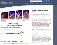 Selecting appropriate coaxial cable and wire for demanding amateur radio applications, particularly those involving high power or harsh environmental conditions, is crucial for maintaining signal integrity and operational safety. This resource details Harbour Industries' specialized offerings, which include Mil-Spec and commercial designs such as NEMA HP3/HP4 and SAE AS22759, suitable for aerospace, military, and industrial sectors. Their product line addresses the need for robust conductors capable of withstanding extreme temperatures and mechanical stress, often encountered in antenna systems or amplifier interconnections. The company highlights its AeroPOWER® Firezone M25038/3 cable, specifically engineered for high-temperature environments like aircraft engines. This particular product exemplifies their focus on solutions for critical infrastructure where reliability under adverse conditions is paramount. Such cables are relevant for hams building or maintaining stations in challenging climates or those operating high-power amplifiers where internal wiring must endure significant thermal loads. Harbour Industries also provides a range of high-performance cables designed to meet stringent specifications. Their expertise in high-temperature and high-performance cable manufacturing positions them as a supplier for specialized wiring needs beyond standard off-the-shelf options, ensuring durability and performance for advanced amateur radio setups.
 -
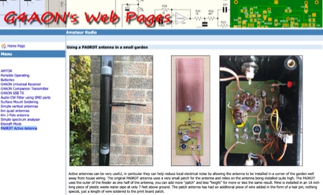 Active antennas can be very useful, in particular they can help reduce local electrical noise by allowing the antenna to be installed in a corner of the garden well away from house wiring. The original PA0RDT antenna uses a very small patch for the antenna and relies on the antenna being installed quite high.
 -
 Over 500 different types of high-performance electronic cables are manufactured by Alpha Wire, catering to demanding industrial and commercial applications. Their product lines include the robust _XTRA GUARD_ series, designed for harsh environments, and a range of flexible coaxial cables optimized for signal integrity. These cables are critical components in amateur radio shacks, industrial control systems, and data communication networks, ensuring reliable power and signal transmission. The company provides extensive technical resources, including detailed product specifications, application notes, and RoHS certificates, accessible through their online resource center. Hams often utilize their wire and cable products for antenna construction, station wiring, and various DIY projects requiring durable and reliable conductors. Alpha Wire also offers tools like size guides and competitor cross-references, simplifying product selection. They emphasize continuous uptime solutions, reflecting their focus on quality and durability.