0 notes &
RF Probes
Another kind of random post! Usually I have a long lasting series of posts on certain topics, but since finishing the Ham Radio License Manual, and starting up First Spin, I’ve been learning a lot of new things about electronics and what can be done with the parts that I already have.
So the germanium diodes were not used for the bridge rectifier, but that’s okay because @trc_wm suggested I make an RF probe with one of them. I can only assume that an RF probe can detect radio frequencies. But let’s look a bit more into this!
What is the point of an RF probe:
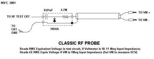
- From this site: It can be used to measure RF voltage (and power), trace RF signals in a new design, and troubleshoot malfunctioning RF circuits.
- From this site: RF probes are normally used with a digital multimeter to indicate the voltage level as dc voltage which is equivalent to the RMS value of the RF voltage being measured.
And from this: You might think of an RF probe as a special test lead that converts your regular ol’ DC voltmeter to a RF reading voltmeter. Why not just read it using your trusty voltmeter, set on AC? Well, because most voltmeters wont read AC signals having a frequency above 10 or 100 KHz, and RF is way above that. This site btw is particularly good to read.
Now you may see the diode flipped in other circuits such as the following. Note, “scope” is supposed to read as multimeter. If you had an oscilloscope, you wouldn’t need an RF probe:
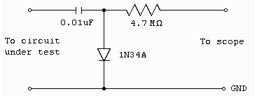
If I’m not mistaken, because this is ac current, the direction of the diode doesn’t really matter. There will always be one direction in which current is allowed to go through - whether that is the positive or the negative half of the AC wave.
So my question is…how does this simple circuit detect RF and how does that become measurable voltage?
Well, in much the same way that most crystal radios are made with germanium diodes, the use of the germanium diode allows for rectification of AC signals present in the circuit. DC signals would be effectively blocked. And according to @brainwagon, the capacitor and resistor act as a low pass filter.
So one lead goes to the RF probe diode and one lead goes from the resistor of the rf probe to the multimeter.
I think I’ll have a video up by the time this post goes up and we’ll do some testing!
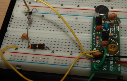
EDIT: Hah. Make sure you put that one wire actually to the capacitor -_-
@atdiy/@tymkrs