Search results
Query: 10 mh choke
Links: 12 | Categories: 0
-
 GM4JMU shortened dipole for 40 meters band. This article illustrates in detail how to build a resonant antenna for 7.030 MHz. Cut two 10.25-meter pieces of insulated wire, wind 40 turns of wire onto plastic tubing, and connect the wire to a central insulator using a choke balun built of RG174AU coax and a ferrite toroid. Once built, the antenna is adjusted by altering the wire length to produce the lowest Standing Wave Ratio (SWR) for best performance. The guide emphasizes careful building and adjustment for the best results.
 -
 This drawing shows a simple 10 meter wire J-pole antenna designed for 28.4 MHz. It is a vertical, end-fed Zepp-style antenna made from common materials and intended for easy home construction. The main radiating element is a straight length of stranded copper wire, either 14 or 18 gauge, cut to about 16.5 feet. At the top, the wire is supported by an insulator, allowing the antenna to be hoisted vertically. The matching section is made from 450-ohm ladder line, approximately 7 feet 9.5 inches long, and shorted at the bottom. This matching stub transforms the impedance so the antenna can be fed with coaxial cable. The feed point is tapped about 6 inches above the bottom of the stub, with the shield and center conductor connected at the proper points. A choke balun is formed with five turns of RG-58 coax in a 4-inch diameter loop to help reduce unwanted RF on the feed line. The drawing notes that this antenna has about 0 dBd gain, similar to a dipole, but offers an omnidirectional pattern and low-angle radiation when installed high. Its main advantage is practical performance, simple construction, and effective coverage for 10 meter operation.
 -
 Demonstrates the construction and performance of an updated ZS6BKW multiband dipole, a variant of the _G5RV_ antenna, specifically designed for HF operation. The article details a real-world installation using 13.5m copper wire elements and 12.2m of 450 Ohm ladder line, configured as a sloping inverted-V with the apex at 10m and ends at 4m above ground. It covers the critical aspect of impedance matching, incorporating an 8-turn choke balun at the feedline transition to RG-58U coax to mitigate RF common mode current. Measurements confirm favorable SWR readings below **1.3:1** on 7.1 MHz, 14.11 MHz, 18.06 MHz, and 24.8 MHz, indicating effective resonance across 40m, 20m, 17m, and 12m bands. The installation also shows usable SWR dips on 3.55 MHz (5:1), 29.02 MHz (2:1), and 50.84 MHz (3:1), extending its utility to 80m, 10m, and 6m with an antenna tuning unit. Initial on-air results report clear reception of stations over **5000km** away, validating its DX potential.
 -
 Demonstrates practical solutions for reducing **Radio Frequency Interference (RFI)** in amateur radio operating environments, specifically addressing issues with PC monitors, receivers, and transceivers. The resource compiles advice from experienced operators regarding the selection and application of ferrite cores, including split cores and toroidal cores. It details specific material types like **43, 73, 75, and 77 ferrite**, outlining their effective frequency ranges for RFI suppression, such as 43 material for 30-400 MHz and 77 material for 2-30 MHz. The content provides part numbers for various ferrite products from manufacturers like Fair-Rite Products Corp, distributed by Amidon, and discusses their impedance characteristics across different HF bands. It compares the performance of various ferrite materials at frequencies like 4 MHz, noting that 75 material offers 27 ohms, 73 material 17 ohms, and 43 material just under 10 ohms. Additionally, it touches upon the use of bypass capacitors in conjunction with ferrites to create low-pass filters, emphasizing the importance of identifying common-mode versus differential-mode RFI paths for effective mitigation.
 -
 The G5RV multiband HF antenna, designed by Louis Varney (G5RV) in 1946, is a popular compromise antenna offering good overall performance on most HF bands when paired with an external antenna tuner. The basic full-size G5RV measures 102 feet across the top for 80 through 10 meter operation and is fed at the center via a 34-foot low-loss feed-stub. This interaction between the radiating section and the feed-stub facilitates matching across 80-10 meters with a standard tuner, often eliminating the need for ladder line directly to the shack. The antenna's design center frequency is 14.150 MHz, configured as a 3/2-wave dipole on 20 meters, with its 102-foot length derived from long-wire antenna formulas. Construction details emphasize the matching section, which can be open wire, ladder line (window-type), or TV twin lead. Each type has a specific velocity factor (VF) affecting its physical length for an electrical half-wave on 14 MHz; for instance, open wire requires 33.7 feet (VF 0.97), ladder line 31.3 feet (VF 0.90), and TV twin lead 28.5 feet (VF 0.82). The article provides formulas for calculating these lengths and discusses the antenna's behavior on individual bands, from 3.5 MHz where it acts as a shortened dipole, to 28 MHz where it functions as two three-half-wave long-wire antennas fed in-phase. Practical construction notes include recommendations for vertical descent of the matching section, sealing the coax junction, providing strain relief, and winding a coaxial choke coil to mitigate common mode current. The resource also presents dimensions for double-size (204 ft) and half-size (51 ft) G5RV versions, along with their corresponding matching section lengths for various line types, making it a versatile reference for hams considering this classic wire antenna.
 -
 Optimizing the ZS6BKW antenna for full HF band coverage often requires specific modifications beyond its standard configuration. This resource details several enhancements, beginning with a simple series capacitor to improve 80m SWR, a technique W5DXP found effective for permanent installation due to its minimal impact on higher bands. Further improvements include a 10-inch parallel open stub for 10m resonance, shifting the frequency to 28.4 MHz with an SWR of approximately 1.8:1, a practical solution for Technician class operators. The document then explores a switchable matching section, adding or subtracting one foot of ladder line at the 1:1 choke-balun, which significantly impacts higher frequency bands and eliminates the need for a tuner on 17m. W5DXP's _AIM-4170D_ antenna analyzer measurements confirm these effects. More advanced modifications involve a parallel capacitor for further 80m SWR reduction, requiring remote switching for multi-band operation, and relay-switched parallel capacitors at specific points on the 450-ohm matching section to achieve low SWR on 60m, 30m, and 15m. These detailed steps, including _Smith chart_ analyses for the challenging bands, aim to transform the ZS6BKW into a truly all-HF-band antenna, reflecting W5DXP's practical experience in antenna tuning.
 -
 The _Sci.Electronics FAQ: Repair: RFI/EMI Info_ document, authored by Daniel 9V1ZV, provides a detailed analysis of computer-generated RFI/EMI, focusing on its impact on radio reception. It identifies common RFI sources such as CPU clock rates (e.g., 4.77 MHz to 80 MHz), video card oscillators (e.g., 14.316 MHz), and even keyboard microprocessors, all of which generate square-wave harmonics across HF and L-VHF regions. The resource outlines a systematic procedure for pinpointing RFI origins, including disconnecting peripherals and using a portable AM/SW receiver with a ferrite rod antenna to localize strong interference sources. The document categorizes RFI mitigation into shielding, filtering, and design problems, offering practical solutions for each. It recommends applying conductive sprays like _EMI-LAC_ or _EMV-LACK_ to plastic casings of radios, monitors, and CPUs to create effective Faraday cages, emphasizing proper grounding and avoiding short circuits. For filtering, the guide suggests using line filters, ferrite beads, and toroids on power and data lines, and small value capacitors (e.g., 0.01 uF for serial/parallel, 100 pF for video) to shunt RFI to ground. It also discusses the use of bandpass, high-pass, low-pass, and notch filters on the receiver front-end or antenna feed to combat specific in-band noise.
 -
 Choking balun for lower HF and MF bands. (1.8MHz - 10MHz). Requiring a choking balun to isolate the potential RF pick up on the coax cable as it runs past equipment such as computer within the radio room at lower HF and MF frequencies a simple method of winding RG58 coax onto a Powdered Iron Toroid Core was constructed.
 -
 A C-Pole Antenna for QRPxpeditions describes a DIY C-Pole antenna designed for QRP (low-power) expeditions, inspired by KF2YN’s ground-independent vertical model. After adjustments, it achieved a 1:1 SWR at 14.060 MHz, rising to 2.5:1 at 14.35 MHz. A choke balun, comprising 15 turns of RG8X around a 4†can, was essential for optimal performance. Compact and self-supporting, the antenna enables reliable communication with minimal setup. Contacts included stations across the U.S., and even a 4,600-mile connection to Spain using only 5 watts.
 -
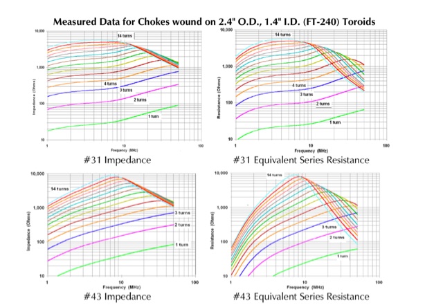 FT-240 toroids measurements. The data was measured using well-calibrated HP instrumentation. All plots have been adjusted to a frequency range of 1-100 MHz on the horizontal axis and a resistance/impedance range of 10-1,000 ohms on the vertical axis. This adjustment facilitates comparison among different materials and aids in determining their suitability for use on the HF ham bands.
 -
 Demonstrates practical **rules of thumb** for selecting and utilizing ferrites and coils in amateur radio projects, particularly for RF applications up to 30 MHz. It addresses common challenges like determining appropriate ferrite grades and estimating L/C values without precise specifications. The resource details the author's experience with readily available grey ferrites, noting their suitability for HF work, and provides guidance on constructing **baluns** and RF chokes, balancing inductance for lower frequencies against inter-wire capacitance for higher frequencies. It also outlines a method for estimating power handling based on ferrite weight, suggesting a 1-gram ferrite can manage over 2 Watts, and offers a technique for evaluating unknown ferrites by winding 10 turns and measuring resonance with a 1 nF capacitor. This approach emphasizes a hands-on, iterative method for balun winding and adjustment, allowing operators to quickly approximate component values. The article compares the characteristics of ferrite-cored coils with air-cored coils, highlighting the reduced pickup and radiation of ferrite designs. It refines the air-coil estimation method for frequencies between 2.5 MHz and 10 MHz and provides a scaling factor for frequencies outside this range, aiming to get operators into the correct general area for their designs. The author's standardized ferrite choice (RND Components 165-00182) is presented as a practical example for reproducible projects.
 -
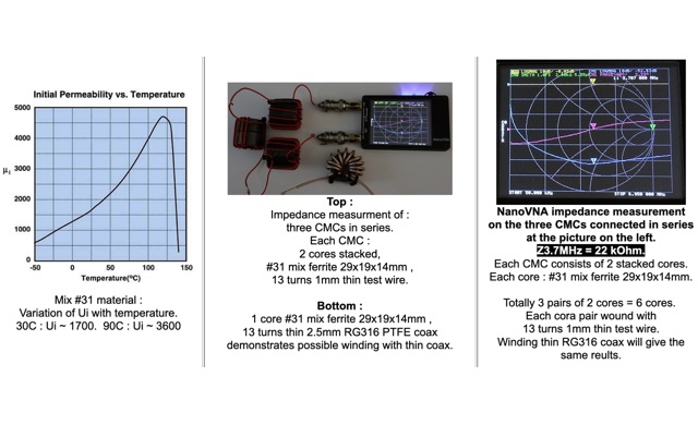 The influence of temperature changes in Common Mode Chokes. To get an indication of the impedance behavior when the core temperature changes, the author tested a CMC by heating it with a hairdryer, and measuring its temperature with an infrared thermometer. When the CMC temperature rises from 30C to 90C, the frequency of maximal impedance shifts down from ca.10 MHz to ca.7.2 MHz, or by a factor 1.4.