Search results
Query: 450 mhz antenna
Links: 17 | Categories: 0
-
 A 10-20 meters coverage delta loop antenna. After relocating, DL2HCB designed a multiband loop antenna to cover 10-20m with an open-wire feed for impedance matching and compact installation. Inspired by the mini-X-Q design, a modified 10m delta-loop was built, enhanced with a 1/4 wave shorted stub for 28 MHz using 450-ohm ladder line. The antenna delivers east-west broadside radiation and performs as a closed loop on other bands. Operational tests yielded strong European signals and successful DX contacts, including a 20m QRP QSO with FY/DJ0PJ.
 -

-
 This drawing shows a simple 10 meter wire J-pole antenna designed for 28.4 MHz. It is a vertical, end-fed Zepp-style antenna made from common materials and intended for easy home construction. The main radiating element is a straight length of stranded copper wire, either 14 or 18 gauge, cut to about 16.5 feet. At the top, the wire is supported by an insulator, allowing the antenna to be hoisted vertically. The matching section is made from 450-ohm ladder line, approximately 7 feet 9.5 inches long, and shorted at the bottom. This matching stub transforms the impedance so the antenna can be fed with coaxial cable. The feed point is tapped about 6 inches above the bottom of the stub, with the shield and center conductor connected at the proper points. A choke balun is formed with five turns of RG-58 coax in a 4-inch diameter loop to help reduce unwanted RF on the feed line. The drawing notes that this antenna has about 0 dBd gain, similar to a dipole, but offers an omnidirectional pattern and low-angle radiation when installed high. Its main advantage is practical performance, simple construction, and effective coverage for 10 meter operation.
 -
 A detailed drawing of a VHF UHF Log periodic antenna by VA2PHI
 -
 Demonstrates the construction and performance of an updated ZS6BKW multiband dipole, a variant of the _G5RV_ antenna, specifically designed for HF operation. The article details a real-world installation using 13.5m copper wire elements and 12.2m of 450 Ohm ladder line, configured as a sloping inverted-V with the apex at 10m and ends at 4m above ground. It covers the critical aspect of impedance matching, incorporating an 8-turn choke balun at the feedline transition to RG-58U coax to mitigate RF common mode current. Measurements confirm favorable SWR readings below **1.3:1** on 7.1 MHz, 14.11 MHz, 18.06 MHz, and 24.8 MHz, indicating effective resonance across 40m, 20m, 17m, and 12m bands. The installation also shows usable SWR dips on 3.55 MHz (5:1), 29.02 MHz (2:1), and 50.84 MHz (3:1), extending its utility to 80m, 10m, and 6m with an antenna tuning unit. Initial on-air results report clear reception of stations over **5000km** away, validating its DX potential.
 -
 The ZS6BKW multiband HF antenna, a design by ZS6BKW (G0GSF), functions effectively on multiple HF bands without requiring an Antenna Tuning Unit (ATU) for 40, 20, 17, 12, 10, and 6 meters. This antenna, approximately **27.51 meters** (90 feet) long with a 12.2-meter (40-foot) open-wire feeder, is a direct descendant of the _G5RV_ but offers superior multi-band resonance. It can be deployed as a horizontal dipole or an inverted-vee, with the latter requiring only a single support and maintaining an apex angle of at least 90 degrees to prevent signal cancellation. Performance data, recorded with an MFJ Antenna Analyser, indicates SWR values of 1:1 on 7.00 MHz (40m) and 14.06 MHz (20m), with SWR below 1.3:1 on 17m, 10m, and 6m. While primarily designed for these bands, the antenna can be adapted for 80m, 30m, and 15m with an ATU, preferably at the balanced feeder's base. The use of 450-ohm twin-lead for the feeder is recommended over 300-ohm for improved strength and reduced losses, especially in adverse weather conditions. This design, originally published in _RadCom_ in 1993 and featured in Pat Hawker’s "Antenna Topics," provides a compact and efficient solution for HF operation, particularly for those with limited space or resources.
 -
 The G5RV antenna, a popular multi-band wire antenna, typically employs a center-fed design with a specific length of 300-ohm or 450-ohm open-wire line acting as an impedance transformer, feeding a coaxial cable run to the shack. Its overall length for 80-10 meters is approximately 102 feet (31 meters) for the flat-top section, with a 34-foot (10.36 meter) matching section. The original design by Louis Varney, G5RV, aimed for efficient operation on 14 MHz (20 meters) as a 3-half-wave antenna, with the matching section providing a good match to 50-ohm coax on that band. While the G5RV offers multi-band capability, its performance varies across bands, often requiring an antenna tuner for optimal SWR on bands other than 20 meters. The matching section's length is critical for its impedance transformation properties, influencing the feedpoint impedance presented to the coaxial cable. Variations like the G5RV Junior and ZS6BKW utilize different flat-top and matching section lengths to optimize performance for specific band sets or to achieve a lower SWR without a tuner on certain bands, demonstrating the adaptability of the basic G5RV concept.
 -
 A 10 meters band Slim Jim antenna project, made with a 450 Ohm slotted ribbon cable and secured on a 8 m fishing pole, by Steve G0KYA
 -
 The ZS6BKW antenna, a popular multiband wire antenna, offers improved band matching compared to the traditional G5RV. This construction guide details the process, beginning with specific dimensions: 13.11 meters (43 feet) for the 450-ohm ladder line and initial dipole arm lengths of approximately 14.8 meters each. It emphasizes the critical role of an _antenna analyzer_ for accurate tuning, particularly for determining the velocity factor of the ladder line and achieving a 1:1 impedance match. The article outlines the materials required, including a 1:1 current balun, 450-ohm window line, wire for the dipole arms, and a 50-ohm non-inductive resistor for testing. It provides a step-by-step procedure for cutting the ladder line to its electrical half-wavelength, explaining how to calculate the velocity factor using measured and free-space frequencies. For instance, a measured 50-ohm impedance at 12.54 MHz with a calculated free-space half-wavelength frequency of 11.44 MHz yields a velocity factor of 0.91. Final adjustments involve hoisting the antenna to its operational height and fine-tuning the dipole arm lengths to achieve optimal SWR, specifically targeting 14.200 MHz. The _ZS6BKW_ design is noted for its performance on 80m, 40m, 20m, 10m, and 6m, though it is not optimized for 15m operation. The author, _VK4MDX_, shares practical tips for durable construction using stainless steel wire and cable clamps.
 -
 Optimizing the ZS6BKW antenna for full HF band coverage often requires specific modifications beyond its standard configuration. This resource details several enhancements, beginning with a simple series capacitor to improve 80m SWR, a technique W5DXP found effective for permanent installation due to its minimal impact on higher bands. Further improvements include a 10-inch parallel open stub for 10m resonance, shifting the frequency to 28.4 MHz with an SWR of approximately 1.8:1, a practical solution for Technician class operators. The document then explores a switchable matching section, adding or subtracting one foot of ladder line at the 1:1 choke-balun, which significantly impacts higher frequency bands and eliminates the need for a tuner on 17m. W5DXP's _AIM-4170D_ antenna analyzer measurements confirm these effects. More advanced modifications involve a parallel capacitor for further 80m SWR reduction, requiring remote switching for multi-band operation, and relay-switched parallel capacitors at specific points on the 450-ohm matching section to achieve low SWR on 60m, 30m, and 15m. These detailed steps, including _Smith chart_ analyses for the challenging bands, aim to transform the ZS6BKW into a truly all-HF-band antenna, reflecting W5DXP's practical experience in antenna tuning.
 -
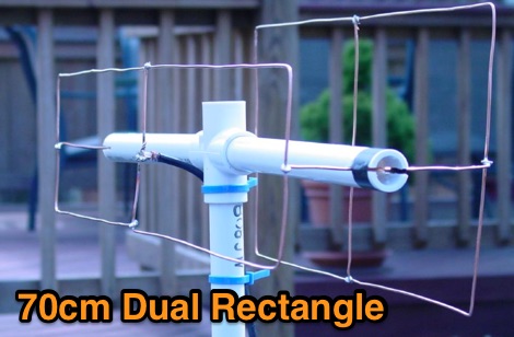 The antenna described here is a direct-connect dual-rectangle beam for use on 70 cm between 440 and 450 MHz
 -
 Documents the construction of a **VHF/UHF** antenna addition for the Buddipole HF antenna system, leveraging the existing Versa-Tee component. The project details the fabrication of a custom antenna mount from angle aluminum, including specific drilling and tapping for 3/16"-24 bolts, and the creation of radials from Simpson Strong Tie Insulation Supports. It specifies radial lengths for 70 centimeters (6 inches from the center stud) and 2 meters (19 1/4 inches), noting the use of wire nuts for safety. The resource outlines the construction of a mast from 1/2" ID PVC conduit, connected with 3/8"-24 connecting nuts and bolts, mirroring the Buddipole's modular design. It describes the integration of a mobile dual-band antenna with a 3/8"-24 mounting stud and the custom coax setup with BNC and **PL-259** connectors. Field testing with an FT-817ND and a separate dual-band SWR meter confirmed good SWR on both 2 meters and the 440-450 MHz section of 70 centimeters, with positive reception reports during Field Day activities. Further, the article describes the creation of a custom carrying solution, including a 22-inch tripod bag and a fabric roll-up, to emulate the portability of the original Buddipole system.
 -
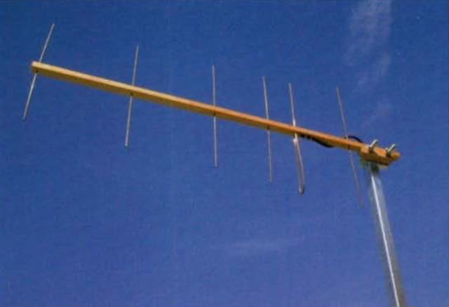 A collection of 450 MHz Cheap Yagis that have proven great portable operations, back-packing and transmitter hunts, and are something inexpensive you can throw up in the attic for that weak repeater
 -
 This J-Pole is mounted on a fishing rod. The radiator L1 is an isolated copper-wire with a length of 281,5 cm while the quarter-wave matching sector L2 is made with 450-Ohm-Wireman-cable
 -
 Dipole for 40m band. It is a simple linear loaded dipole feeded with 450-Ohm openwire feedline. Designed it for resonance at 7.050 MHz, can be tuned on 30m and 80m bands with an external antenna tuner. Build with simple electrical copper wire (2.5 mmq/13 awg) and two fishing poles with size of about 7 m/23 ft.
 -
 This article details the author's process of designing and building a trap dipole antenna for the 17, 12, and 6-meter amateur radio bands using a Yaesu FT-450 transceiver. The antenna incorporates parallel-tuned circuit traps to enable operation across multiple bands without switching aerials. Key construction details, including coil and capacitor specifications, are discussed, along with the testing results, which include successful long-distance communications on the 50 MHz band. The article highlights the flexibility of home-built antennas and provides insights for amateur radio enthusiasts looking to optimize multi-band performance.
 -
 The PA0FRI Unbalanced/Balanced ATU is a home-built antenna tuner designed to efficiently match a W8JK 2-element beam antenna fed with a 450-ohm twin lead. Based on PA0FRI’s S-Match design, it optimizes energy transfer while maintaining balance, reducing losses, and ensuring proper radiation. The tuner uses a roller inductor, air variable capacitors, and a T200 iron powder coil, allowing fine-tuning across 14-50 MHz. Extensive lab tests confirm minimal attenuation and precise impedance matching, making it a reliable and efficient ATU for balanced antennas.