Search results
Query: how to build a magnetic
Links: 8 | Categories: 0
-
 Documents and schema on how to build a Magnetic Loop Antenna fo 80/30 mtrs
 -
 An easy guide to "How to build your own magnetic loop" for 20 meters
 -
 The BikeLoop antenna project details the construction of a double magnetic loop antenna optimized for VLF frequencies, specifically around 136 kHz. This innovative design incorporates two orthogonal loops, which significantly enhance reception capabilities. Key construction hints include utilizing lightweight bicycle rims for the antenna structure, making it easy to transport and set up in various locations. The document provides valuable mathematical and electrical insights into the antenna's performance, alongside practical reception tests conducted in the Italian Alps, showcasing its effectiveness in capturing various VLF signals, including Sferics and FSK transmissions. Proper setup is crucial for optimal performance. The project emphasizes the importance of grounding and avoiding interference from nearby electrical sources. The reception tests revealed the antenna's ability to capture a range of signals, demonstrating its practical application for enthusiasts interested in VLF reception and antenna experimentation. Overall, the BikeLoop serves as an excellent starting point for those looking to explore the world of VLF frequencies and enhance their antenna-building skills.
 -
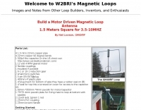
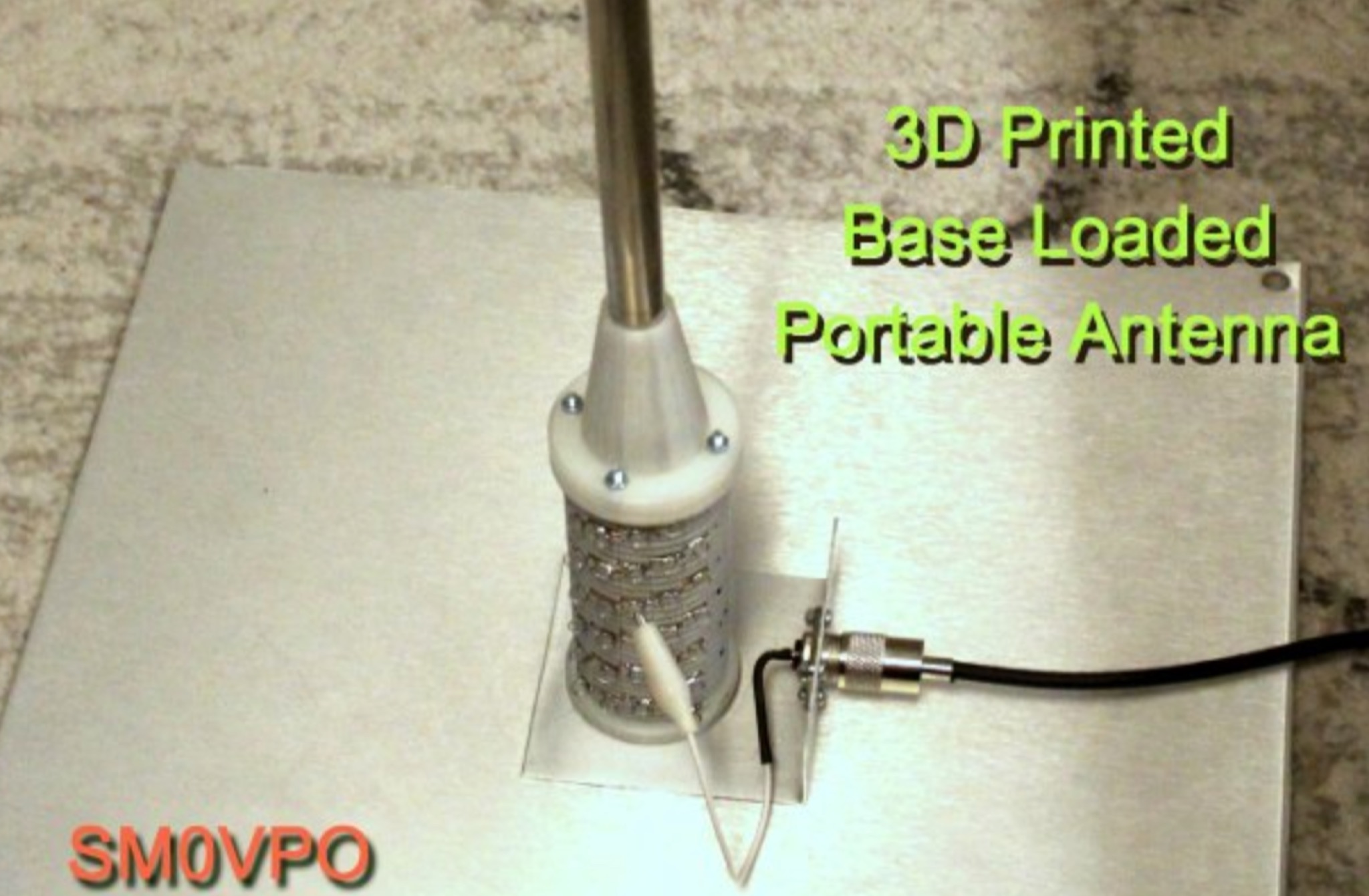
 This article shares the author's experience with building antennas. After putting a large magnetic loop project on hold, they decided to try a base-loaded vertical antenna. The author explains how they chose to design a new antenna from scratch, aiming for a frequency of 7 MHz. They describe the calculations needed to find the right coil inductance and how they used 3D-printed parts for the construction. The article wraps up with results from their initial tests, showing good communication on different bands and highlighting the success of their design.
 -
 This page by Keith Greiner describes a magnetic loop antenna project, providing step-by-step instructions to create two versions of a system with one large loop and one small loop. It includes details on how to construct the loops using different materials, along with the necessary equipment like antenna analyzers, tuners, and software. The page is divided into five sections covering project discussion, design summary, an improved small loop, construction steps, and radiation pattern analysis. Aimed at hams interested in building their own magnetic loop antennas, the page offers practical guidance and insights into impedance matching for improved performance.
 -
 This article describes the phases for the construction of a Yagi antenna. The calculations of the parameters are made using 4NEC2 software. This type of antenna is used for transmissions and receptions of electromagnetic waves. The project shown here refers to the frequency of 433.92 MHz.
 -
 Learn how to build a compact and efficient HF antenna for ham radio operators with limited space. Follow the author's journey from experimenting with different antennas to creating a magnetic-mounted antenna that covers 7MHz to 30MHz without the need for an ATU. Discover how a portable flagpole can be repurposed for radio communication, allowing you to operate with 100 Watts power output. This project provides a cost-effective solution for hams looking to set up a reliable antenna on their car roof in just 30 seconds.
 -
 Chavdar Levkov, LZ1AQ, presents an experimental comparison of small wideband magnetic loops, building on his previous work on wideband active small magnetic loop antennas. His research focuses on increasing loop sensitivity by maximizing the short-circuit current, which is directly tied to the "loop factor" M = A/L, where A is the equivalent loop area and L is its inductance. Levkov's methodology involves reducing inductance and increasing area through parallel or coplanar crossed (CC) configurations, comparing these designs against a reference single quad loop of 1 m2 area. Experimental verification included testing three distinct loop types: a simple quad loop, two coplanar crossed (CC) loops, and eight parallel loops, all designed to have a total geometric area of 1 m2. Measurements were conducted at 1.8, 3.5, 7, and 10 MHz using a small transmitter 270 meters away, with a Perseus direct sampling receiver for precise signal level assessment. The results consistently showed that CC loops, particularly Loop 5 (two CC circular loops with 1.44 m2 total area), yielded significantly higher currents, up to 9.1 dB over the reference loop at 3.5 MHz, validating M as a reliable predictor of loop sensitivity. Numerical simulations using MMANA further corroborated the experimental findings, demonstrating an almost perfect correlation between the calculated M factor and the induced loop current for 15 different loop models. Levkov concludes that CC loops offer superior sensitivity for a given loop area, while parallel loops are advantageous for minimizing physical volume. Practical recommendations suggest using loops with an M factor greater than 0.5 uA/pT for quiet rural environments, and he provides a spreadsheet tool, WLoop_calc.xls, to aid in optimizing loop configurations for specific operational needs.