Search results
Query: kenwood wiring
Links: 7 | Categories: 0
-
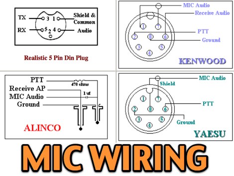 11 most popular MIC wiring diagrams including AZDEN Alinco Icom Kenwood Yaesu Astatic Cobra Sadelta Turner microphens diagrams and pin-end views
 -
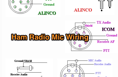 Kenwood Alinco and Icom amateur radio transceivers - Mic Wiring diagrams by pictures
 -
 Roy G4WPW has collected one of the most complete and interesting pages for microphone connections schemas and wiring. Includes Kenwood microphones schematics as well as Yaesu Icom Alinco Adonis Drake Heil JRC MFJ schematics
 -
 The resource provides a specific wiring schema for adapting a Kenwood PG-4S cable to be compatible with Kenwood TH-F6A, TH-F7E, and TH-G71 handheld transceivers. It details the necessary pinout modifications, illustrating how to convert the existing PG-4S cable, which is typically used for data transfer or programming, into an interface cable for these specific HT models. The content focuses on the electrical connections required to achieve this cross-compatibility, presenting a practical solution for hams who already own a PG-4S and wish to avoid purchasing additional dedicated cables for their TH-F6A, TH-F7E, or TH-G71 radios. The adaptation process involves reconfiguring the connections to match the audio and data port requirements of the target handhelds. This technical information is particularly useful for operators seeking to interface their Kenwood HTs with sound cards for digital modes or for programming purposes, leveraging existing hardware. The page offers a direct, functional approach to hardware modification, emphasizing reusability and cost-effectiveness for Kenwood transceiver owners.
 -
 This online guide details the microphone pinout for the Kenwood TR-7950 transceiver, specifically addressing the wiring configuration for a dynamic mobile microphone with a **500 Ohm** impedance. It provides a pin-by-pin breakdown for the 6-pin microphone connector, identifying the function of each active pin. The resource specifies that Pin #1 is for the microphone audio (white wire), Pin #2 controls the _PTT_ (black wire), Pin #3 activates the memory down function (blue wire), and Pin #4 controls the memory up function (red wire). Pin #6 is designated as the ground connection, while Pin #5 remains unused in this configuration. The document focuses on the physical wiring necessary to restore microphone functionality to the Kenwood TR-7950, a transceiver capable of **45 watts** output on the _2m band_. It directly addresses the technical challenge of re-establishing correct electrical connections after microphone wires have been disconnected from the connector. The information facilitates proper microphone operation for simplex QSOs and other voice communications. DXZone Focus: Online Guide | Microphone Pinout | Kenwood TR-7950 | PTT Wiring
 -
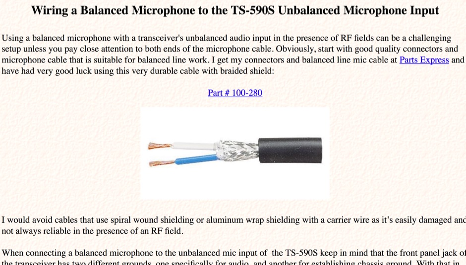 Wiring a Balanced Microphone to the TS-590S Unbalanced Microphone Input
 -
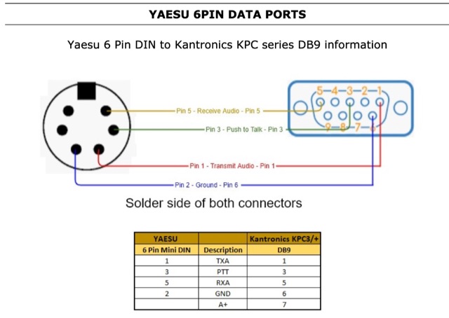 Kantronics Pinouts with information on Icom, Kenwood Motorola, Yaesu and Vertex radio connections.