Search results
Query: qrp antenna tuner for 30
Links: 4 | Categories: 0
-
 This PDF article from April 2001 QST details the construction of the "NJQRP Squirt," a reduced-size 80-meter inverted-V dipole antenna. The resource provides a general construction sketch, a photograph of the assembled antenna, and specific dimensions for PC-board insulators. The antenna consists of two wire legs, each approximately **34 feet long**, separated by 90 degrees, fed at the center. It is designed for operation on 80 meters (3.5-4.0 MHz) as a quarter-wavelength antenna, requiring a low-loss feedline and an external antenna tuner due to its non-resonant feedpoint impedance. Construction utilizes readily available materials, including 1/16-inch glass-epoxy PC board for end and center insulators, and #20 or #22 insulated hookup wire for the elements. The feedline specified is 300-ohm TV flat ribbon line, with a note on potential trimming for tuner compatibility. N2CX reports the antenna's center should be elevated to at least **20 feet**, with ends no lower than seven feet above ground, resulting in a ground footprint of approximately 50 feet wide. The design prioritizes NVIS propagation for local 80-meter contacts. DXZone Focus: PDF Article | 80m Inverted-V Dipole | Construction Notes | 34 ft element length
 -
 End-Fed Half-Wave Antennas (EFHWAs) are analyzed for their utility in portable QRP operations, emphasizing their simplicity, efficiency, and predictable radiation patterns compared to other portable antenna types. The discussion contrasts EFHWAs with vertical antennas, random length wires, and center-fed dipoles, highlighting the common pitfalls of each, such as ground system dependency for verticals and feedline issues for dipoles. The article details the electrical half-wavelength calculation using the formula L (Ft) = 468/F(MHz) and explains how EFHWAs can be resonant on harmonic frequencies, enabling multiband operation. Various deployment configurations are presented, including the inverted L, inverted Vee, sloping wire, and vertical setups, each with specific advantages for radiation angle and polarization. For instance, a vertical EFHWA offers a low angle of radiation suitable for DX contacts without requiring an extensive ground system. The resource also addresses the counterpoise requirements, suggesting a quarter-wavelength wire or connection to a metallic structure for decoupling. A schematic diagram for a simple parallel-tuned circuit tuner, based on the _Rainbow Bridge/Tuner_ design, is provided, detailing component values for 30 and 40 meters, including a 6 microhenry toroidal inductor and a 20-100 picofarad mica compression capacitor. The tuner's adjustment process for SWR matching is also outlined.
 -
 The MFJ-971 portable antenna tuner, as stock, lacks a bypass switch and sufficient inductance for efficient 1.8 MHz operation. This modification addresses these limitations by integrating a DPDT switch for direct signal bypass, enhancing operational flexibility. Furthermore, the guide details the addition of a T130-2 iron powder toroid, wound with **29 turns** of enamelled copper wire, to augment the tuner's internal inductance. This increases the maximum inductance from approximately 17µH to around **27µH**, enabling effective impedance matching on the _160-meter band_. The modification involves cutting the wire after the 'L' tap on the original inductor and inserting the additional toroid, ensuring the entire original coil plus the new inductance is engaged when 'L' is selected. This preserves the functionality of other inductance settings while extending low-band performance. The article also highlights a potential RF burn hazard from the variable capacitor nuts on the MFJ-971, even at QRP power levels.
 -
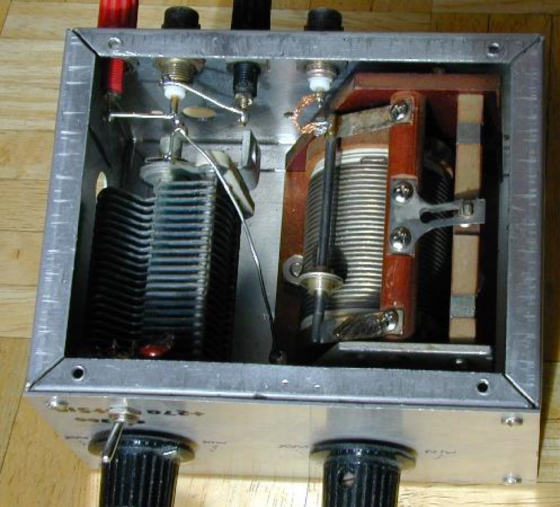 This is a project aboout compact and portable a QRP antenna tuner for use in the HF ham radio bands from 3-30 MHz, even if it's a compact and efficient project this small antenna tuner will not match any possible load.