Search results
Query: l-band
Links: 71 | Categories: 9
Categories
- Radio Equipment > VHF-UHF Handhelds > Baofeng UV-3R
- Manufacturers > Antennas > VHF UHF Microwave > HT Antennas
- Radio Equipment > VHF-UHF Mobile > ICOM IC-2720H
- Radio Equipment > VHF-UHF Handhelds > Icom ID-51A
- Radio Equipment > VHF-UHF Handhelds > Kenwood TH-D7A-E
- Radio Equipment > VHF-UHF Amplifiers > Mirage BD-35
- Antennas > Morgain
- Radio Equipment > VHF-UHF Handhelds > Wouxun KG-UV8D
- Radio Equipment > HF Transceivers > Yaesu FT-991
-
 An Easy Dual-Band VHF/UHF vertical Antenna made with a TV twin lead and coax cable
 -
 A 1/4 wavelength resonator design for dual-band VHF/UHF operation is presented, focusing on a robust mobile antenna construction. The design prioritizes stability against environmental influences over raw gain, making it suitable for general use rather than marginal signal areas. It details the antenna's two sections: a UHF-resonant lower conductor and an upper coil functioning as an RF choke for UHF and an inductance enhancer for VHF, forming a resonant circuit. Detailed mechanical structure and material considerations are provided, including the use of a PL-259 plug base, 2mm copper rod, and PVC faucet tube for the coil form. The guide outlines a precise construction procedure, from soldering the copper rod to the PL-259 to winding the 22 SWG laminated wire for the VHF section. Tuning involves careful cutting of the UHF section and adjusting the coil length and pitch for VHF, using a reflectometer and temporary ground planes. Furthermore, the resource describes converting the mobile antenna for base station application by constructing a dual-band ground plane system. This involves using electrical conduit, EMT connectors, SO-239 sockets, and a 4-inch round-pan with threaded stainless steel rods as ground elements. Practical test results indicate optimal lengths of **70mm** for UHF and **350mm** for VHF ground elements, with a recommendation to cut rods with _30mm_ extra length for fine-tuning.
 -
 About G5RV antennas, with radiation pattern produced with eznec
 -
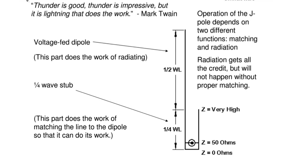 How to Build a Dual-Band Antenna for 2M/70cm presentation PDF file
 -
 A simple and cheap dualband j-pole antenna for 144 and 430 MHz
 -
 The Flower Pot Antenna project details a portable dual-band antenna primarily operating on 10 meters, with secondary resonance near the 30-meter band. Construction involves winding RG58 coaxial cable uniformly around a large plastic flower pot, approximately 70cm high with a 60cm top diameter. The design eliminates the need for radials, contributing to its compact and lightweight nature. Key construction steps include soldering the inner conductor to the shield at one end of the wound cable and connecting the wound cable's shield to the rig cable's inner conductor at the base. An LC network, comprising a variable capacitor (0-200pF) and an inductor (10 coils, 5cm diameter, 2mm wire), is inserted between the wound cable's inner conductor and the rig cable's shield. Tuning is performed with an antenna analyzer, adjusting cable length and the variable capacitor for optimal impedance on 10 meters. The antenna performs effectively when installed horizontally.
 -
 Constructing a **reduced-size coaxial Moxon rectangle** antenna for the 17-meter band is detailed, presenting a method to achieve a compact directional antenna. The resource outlines the use of RG-58/U coaxial cable for elements, enabling a substantial reduction in physical dimensions compared to traditional wire or tubing Moxon designs. It provides specific instructions for tuning coaxial elements using an **MFJ-259B antenna analyzer**, including a formula to calculate trimming lengths based on measured resonance and desired frequency. The article explains how to prepare the coaxial cable for both driven and reflector elements, specifying connections for testing and final assembly. Performance data from an MFJ-259B shows SWR readings between 1.0 and 1.2 across 18.068 MHz to 18.168 MHz, with R values from 51 to 59 ohms and X values of 0 or 6 ohms. The antenna's power handling is approximately 500 watts continuous, limited by the RG-58/U coax. Comparative receive testing against an All-Band Sterba Curtain at 50 feet indicated a 2 S-unit reduction for the coaxial Moxon at 9 feet, suggesting optimal performance at a height of 34-40 feet for a 15-18 degree take-off angle. The design achieves an electrical quarter wavelength with over 30 percent size reduction.
 -
 A dual-bander for 80M and 40m. An Extended Double Zepp (EDZ) is a 5/4 wavelength center-fed dipole. This article will introduce the Half-Extended Double Zepp (HEDZ) which has characteristics that a lot of amateur radio operators should find quite interesting
 -
 The _Morgain_ antenna for 40/80 meters is a straightforward and cost-effective wire antenna design, requiring careful tuning for optimal performance across two bands with low SWR. Construction involves creating 12 cm PVC spacers with three holes for wire insertion, along with larger terminals for anchoring and connector housing, which should be sealed with silicone. The provided measurements detail the specific lengths for the antenna elements, crucial for achieving resonance on both 40m and 80m bands. Tuning the Morgain antenna necessitates fabricating four wire segments with pins to temporarily connect and adjust the bridging points symmetrically for both 40m and 80m. This iterative process, though time-consuming, ensures the antenna functions effectively for decades once the precise connection points are soldered and protected. The design emphasizes ease of construction and long-term stability, making it a practical solution for hams seeking a dual-band wire antenna.
 -
 The KD6WD Moxon Antenna Project details the construction of 50-ohm two-element wire beam antennas, specifically Moxon rectangles, for the 10, 15, 17, and 20-meter bands. It utilizes AC6LA's software for critical measurement calculations (A-E) based on center frequency and wire size. Construction involves 16-gauge silver-coated copper wire, 16-foot telescoping fiberglass crappie fishing poles as spreaders in an "X" configuration, and various hub designs including aluminum tubing or PVC joints. A 1:1 current balun is used at the feedpoint, with wire nuts for connections, often achieving a 1:1 SWR across the design band. The project highlights practical applications, such as running a kilowatt into the antennas for greyline DX contacts, consistently yielding excellent signal reports. Comparisons to quad loops show 4 to 5 S-unit improvements in both receive and transmit. The Moxon design, according to L.B. Cebik's analysis, offers superior forward gain and front-to-back ratio among wire beams. The author notes a "DX-Vane" effect where a freely suspended Moxon automatically points to the strongest DX signal. Attempts at dual-band operation (17/20 meters) with a single feed were unsuccessful, reinforcing the Moxon's monoband nature, with EZNEC plots provided for a 17-meter Moxon at 30 feet.
 -
 A simple dipole built for two-band operation can be used for portable use and operate 20 and 40 meter bands
 -
 The resource details the construction and performance of a dual-band 40/30 meter _Moxon_ antenna, evolving from an initial single-band 30-meter design that failed in a storm. It specifies materials such as four 10-meter fishing rods, galvanized iron TV antenna support pipes, 1mm diameter PVC-covered copper wire, and a piece of 75-ohm TV satellite cable for feedline. The document outlines the iterative design process, including initial resonance measurements of 9.9 MHz for 30 meters and subsequent recalculations to shift the center frequency by 300 kHz using _Moxon software_. Initial testing on a roof yielded SWR readings of 1.4:1 at 7.200 MHz and 1.5:1 at 10.280 MHz. After installation atop a 30-meter tower, the final SWR measurements were 1.1 at 7.130 MHz and 1.4 at 10.230 MHz, with a notable 30 dB front-to-back ratio on 40 meters. The 30-meter performance, while good, showed a front-to-back ratio of approximately 15 dB, suggesting a slightly high resonance. The antenna's placement on a 700-meter hill, with a significant ground drop in certain directions, is noted as a potential factor in its excellent DX performance, enabling daily contacts with the USA West Coast on 30 and 40 meters with 100 watts.
 -
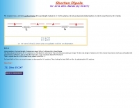 A shorten Dual-Band Dipole with overall length of about 11 m. For this antenna traps are substituted by inductors, in order to cover the 10 & 40 m. Bands.
 -
-
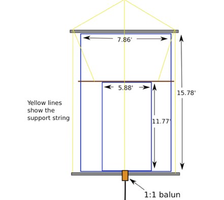
 This PDF document, authored by KT4QW in October 2004, details the construction and modeling of a dual-band, horizontally polarized hanging rectangular loop antenna for **10 and 17 meters**. The design, adapted from *The ARRL Handbook*, utilizes _NEC4WIN95_ software for scaling and optimization, targeting a 50 ohm feedpoint impedance. The resource includes a bill of materials, step-by-step construction instructions, and a discussion of the antenna's radiation characteristics. It presents NEC-generated elevation and azimuth patterns, comparing the loop's performance to a half-wave horizontal dipole at the same height and frequency. The 17-meter element is centered at 18.140 MHz for low SWR across the phone band, while the 10-meter element is centered at 28.500 MHz. Construction involves 14-gauge stranded copper wire and Schedule 40 PVC spreaders, with the total wire length calculated by the formula: Length in feet = 1005/MHz. The feedpoint impedance can be adjusted by modifying the rectangular aspect ratio. The document specifies hoisting the antenna to at least a half-wave above ground for testing. It notes that a balun was tested and found to have no measurable effect on SWR or radiation characteristics. A 2-meter scale model is presented to illustrate the physical design, and a "rotator" string is incorporated for directional adjustment up to 90 degrees.
 -
 Operating on the 12-meter and 17-meter WARC bands often benefits from directional antennas that offer gain and front-to-back ratio in a compact footprint. This resource details the construction of a dual-band wire beam, specifically a _Moxon Rectangle_ design, for these two bands. It outlines the use of fiberglass tubing for spreaders, _Flexweave_ wire for the elements, and an aluminum hub with die-cast flanges to create a robust structure. The design allows for a single 50-ohm feed point, simplifying station setup and minimizing feedline loss. The project provides specific dimensions and material choices, enabling a homebrewer to replicate the antenna. While inspired by L.B. Cebik's (W4RNL) theoretical work, this implementation focuses on practical construction techniques for a physical build. The resulting antenna offers directional characteristics suitable for DXing and contesting on 12m and 17m, providing an alternative to full-sized Yagis or compromise verticals, particularly for those with limited space.
 -
 This technical note explores the application of **Moxon rectangle** antennas for WARC bands, specifically 17 and 12 meters, as compact directional alternatives to standard Yagis. It details three design approaches: a dual-band Moxon using open-sleeve coupling, a Moxon-Yagi combination, and a simplified 1.5 Moxon rectangle. The document provides specific dimensions in feet for aluminum tubing elements (0.75" and 0.5" diameter) for each configuration, along with projected free-space gain, front-to-back ratio, and feedpoint impedance (R+/-jX Ohms) across the respective band segments. Performance tables illustrate gain (dBi), front-to-back ratio (dB), and 50-Ohm VSWR for each design. The dual-band Moxon, despite its compact 7-foot boom, is not recommended due to extreme sensitivity to construction variations, leading to rapidly changing performance characteristics. The Moxon-Yagi combination, featuring a 17-meter Moxon and a 12-meter director-driver Yagi, is presented as a more practical and adjustable solution, offering stable performance with a 10-foot boom. NEC model descriptions are included for simulation in programs like EZNEC, NEC-Win Plus, AO, or NEC4WIN.
 -

-
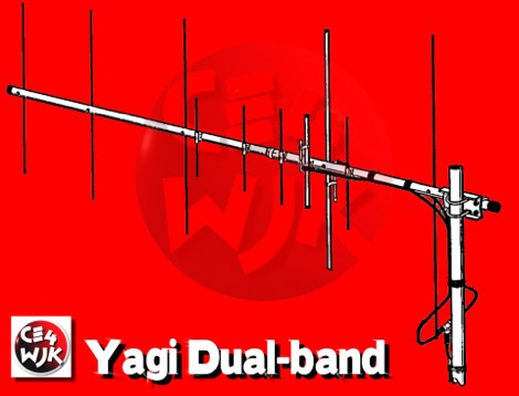
 Antenna was designed for SO-50 satellite operation but can be used for any VHF/UHF activity. It's a mix of a Moxon Antenna and a Yagi antenna. It has gains 4 dBd on 2m and 6.5 dBd on 70cm bands and it is fed via single 50 Ohm cable.
 -
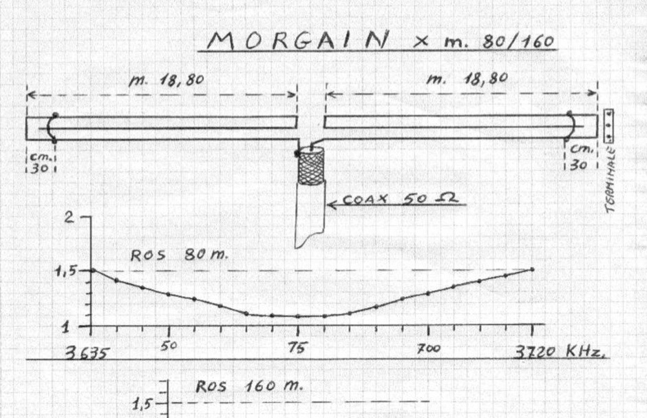 A 37.6-meter Morgain antenna design provides dual-band operation on 80 and 160 meters without traps. The antenna uses 1.5 mm² stranded copper wire with vinyl insulation, commonly found as domestic electrical wire. Tuning involves adjusting lateral jumper wires for the 80-meter band, with initial positions 30 cm from the arm ends, yielding 3635–3715 kHz resonance with SWR below 1.5:1. For 160 meters, a straight wire length of 18.80 meters per arm is critical, achieving 1840–1850 kHz resonance with SWR below 1.1:1. The Morgain antenna exhibits a 50-ohm feed-point impedance, allowing direct connection of 50-ohm coaxial cable like RG-8X, which handles approximately 500 watts. Spacers and the central plate are constructed from 1 mm thick green fiberglass laminate, with spacers measuring 11 cm and installed every 1.90 meters. The central plate is 11 × 11 cm, designed to secure the coaxial cable mechanically. End supports utilize 3–6 mm thick bakelite terminal spacers, tensioned with nylon ropes.
 -
-
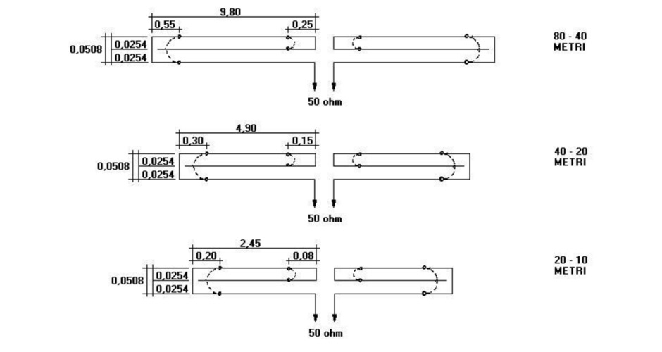 The resource details the historical development of the Morgain antenna, tracing its origins to Virginia in the 1960s and its subsequent global adoption among radio amateurs. It describes the Morgain as a dual-band wire antenna known for its reduced footprint and modest gain characteristics. The content includes discussions on various homebrew projects and design variations available online, providing context for its continued relevance in amateur radio. The article presents a historical overview rather than specific construction plans, focusing on the antenna's evolution and general design principles. It highlights the antenna's enduring appeal due to its performance attributes and compact size, making it suitable for various operating environments.
 -
 This document details the design and construction of a Vinecom 6N4 dual-band Yagi antenna for the 50MHz (6-meter) and 70MHz (4-meter) amateur radio bands. The antenna features 9 total elements (4 elements for 50MHz, 5 elements for 70MHz) on a 4.236-meter aluminum boom. Computer simulations using MMANA software predict 7.21 dBd gain on both bands with front-to-back ratios of 16.01dB (6m) and 15.37dB (4m). The design uses 12.7mm diameter elements mounted on a 32mm square boom, weighing 5.7kg total. Practical measurements with an MFJ-269 analyzer confirmed good SWR performance across both bands after element length adjustments.
 -
-
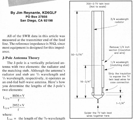
 The resource presents a detailed schematic for constructing a dual-band vertical antenna, specifically designed for operation on the 2-meter and 70-centimeter amateur radio bands. It illustrates the physical layout, critical dimensions, and component placement necessary for successful replication. Key elements such as the radiating elements, phasing sections, and feed point are clearly depicted, providing a visual guide for radio amateurs undertaking a homebrew antenna project. The diagram specifies the lengths for the VHF and UHF sections, indicating how these elements are integrated to achieve dual-band functionality from a single coaxial feedline. It also implies the use of common materials readily available to most experimenters, focusing on simplicity and effectiveness in its design. The visual format of a GIF image ensures direct access to the construction details without requiring extensive textual interpretation. This schematic serves as a practical reference for hams interested in building a compact, efficient vertical antenna for local and regional FM communications, offering a proven design for immediate implementation.
 -
 The G7FEK Multi-Band Nested Marconi Antenna, a small, efficient all-band antenna.
 -
 The ZS6BKW multiband antenna, an optimized variant of the classic G5RV, features a 102-foot (31.1 m) horizontal span and a 39.1-foot ladder line matching section. This design, derived by G0GSF (formerly ZS6BKW) in the early 1980s using computer programs and _Smith charts_, aims for improved SWR across multiple HF bands compared to its predecessor. Construction details specify Wireman 554 ladder line and #14 AWG THHN copper wire for the radiators, with precise instructions for determining the velocity factor (VF) of the ladder line using an antenna analyzer or dip meter, ensuring accurate physical length for the matching section. The radiator length is electrically 1.35 wavelengths for the 20-meter band, requiring careful trimming during tuning. Field measurements with an _AIM-4170C_ analyzer by KI4PMI and NC4FB demonstrated good SWR curves and bandwidth on 6, 10, 12, 17, 20, and 40 meters. The antenna was deemed unusable on 15 and 30 meters due to very high SWR, but an LDG AT-100PRO autotuner successfully brought 6 and 80 meters into tune. Contacts were made on 80, 40, 20, and 17 meters, including a **17-meter** contact to Spain. EZNEC models for 80-6 meters are provided, along with an AutoEZ model by AC6LA, which predicted good SWR for 80-10 meters. W5DXP's modifications for an all-band HF ZS6BKW are also referenced.
 -
 This Z-Match is a link coupled all-band tuner. Two all band tank circuits cover 3-14mhz and 14-30mhz. The tank output links are selected with a very heavy duty SPDT rotary switch.
 -
 The 10-minute, 25-second video demonstrates making a QSO via the VO-52 amateur radio satellite, focusing on real-time Doppler shift correction. It features Simon, 2E0HTS, operating a Yaesu FT-847 transceiver and a homebrew dual-band Yagi antenna, specifically a 10-element 435 MHz Yagi for uplink and an IO Loop for 145 MHz downlink. The video visually details the operator's technique for continuously adjusting the uplink frequency to compensate for the satellite's changing velocity relative to the ground station, a critical aspect of successful satellite communication. The demonstration highlights the practical application of Doppler compensation, showing the operator tuning the transmit frequency to maintain a stable received signal from the satellite. This approach contrasts with systems employing automatic Doppler correction or full-duplex operation, providing insight into manual frequency management for satellite passes. The video serves as a direct, observational guide for hams interested in LEO satellite operations, particularly those using non-tracking, manually tuned setups.
 -
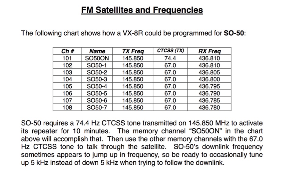 If you can program split-frequency memories in your dual-band radio, or your dual-band radio has two VFOs, you can work an FM satellite
 -
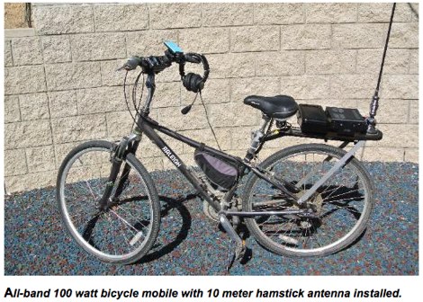 A bycicle ham radio station setup, with full band coverage
 -
 VHF UHF half wave flower pot antenna project by VK2ZOI
 -
 Designing and constructing portable wire antennas for HF operations, this resource explores several configurations including the _foldback dipole_ for space-constrained setups and an inductively shortened dual-band dipole for 20m and 40m. It details the calculation of inductance for shortened elements, providing a Visual Basic 6.0 program screenshot that illustrates determining coil parameters like turns and length for a **25.5 uH** inductor. The document emphasizes practical considerations such as adjusting wire lengths for optimal SWR, noting that a dual-band dipole achieved SWR below 2:1 on both 20m and 40m, with careful adjustment bringing it under 1.5:1. Further, the resource describes a half-wave antenna matched with a coaxial stub, a method often referred to as the _Fuchskreis_ in German amateur radio circles, to transform the high feedpoint impedance to 50 Ohms. This monoband solution, for a 20m application, uses a stub length of **2.98m** (0.216 lambda multiplied by coax velocity factor) and a shorted stub of approximately 48cm. The coaxial stub design is highlighted for its resilience to ground proximity, allowing it to be rolled up or laid on the ground with minimal SWR impact, making it highly suitable for portable QRP operations.
 -
 Design for a dual-band CW transceiver using the AD9834 Direct Digital Synthesizer
 -
-
 Demonstrating the construction of a short dipole antenna tailored for the 60 meter band, this resource provides detailed instructions for radio enthusiasts with limited space. The design incorporates inductive loading using two inductors (L1/L2) made from PVC tubes, allowing for effective operation on 5 MHz. The antenna consists of 12 meters of wire, divided into four sections, with specific dimensions and materials outlined for optimal performance. Results from users indicate that this antenna can significantly enhance DXing capabilities on the 60 meter band. Feedback from operators suggests that while the design is effective, adjustments may be necessary based on individual setups, such as coil diameter and wire gauge. Many users report successful construction and operation, with some experimenting with variations to improve resonance. The practical application of this antenna design has led to successful contacts and improved signal quality, making it a popular choice among 60 meter band operators.
 -
 This resource details the construction of a Moxon rectangle antenna, a two-element wire beam, drawing inspiration from a _QST_ article by Allen Baker, KG4JJH, and a project group led by KD6WD. It outlines the use of _AC6LA_ software for critical measurements (A-E) to design the antenna for specific bands like 17 meters, emphasizing the simplicity of adjusting frequency and wire size. The guide covers material selection for spreaders, such as telescoping fiberglass fishing poles, and various hub constructions, including aluminum tubing and PVC joints, with accompanying images. The author shares practical insights from building multiple Moxons for 10, 15, 17, and 20 meters, noting consistent 1:1 SWR at design frequencies and broadbanded performance. It describes the feedpoint assembly using a 1:1 Yagi current balun and wire nuts for robust, adjustable connections. The resource also discusses element insulators made from Lucite strips and attachment methods to spreaders using plastic wire ties and duct tape, ensuring precise element spacing. Performance observations include significant signal improvements (4-5 S units) over quad loops and a unique "DX-Vane" effect where the suspended antenna self-aligns with the strongest DX signal. The author also recounts an unsuccessful attempt at a dual-band 17/20 meter Moxon, concluding that the Moxon is inherently a monoband antenna, supported by _EZNEC_ plots for a 17-meter design.
 -
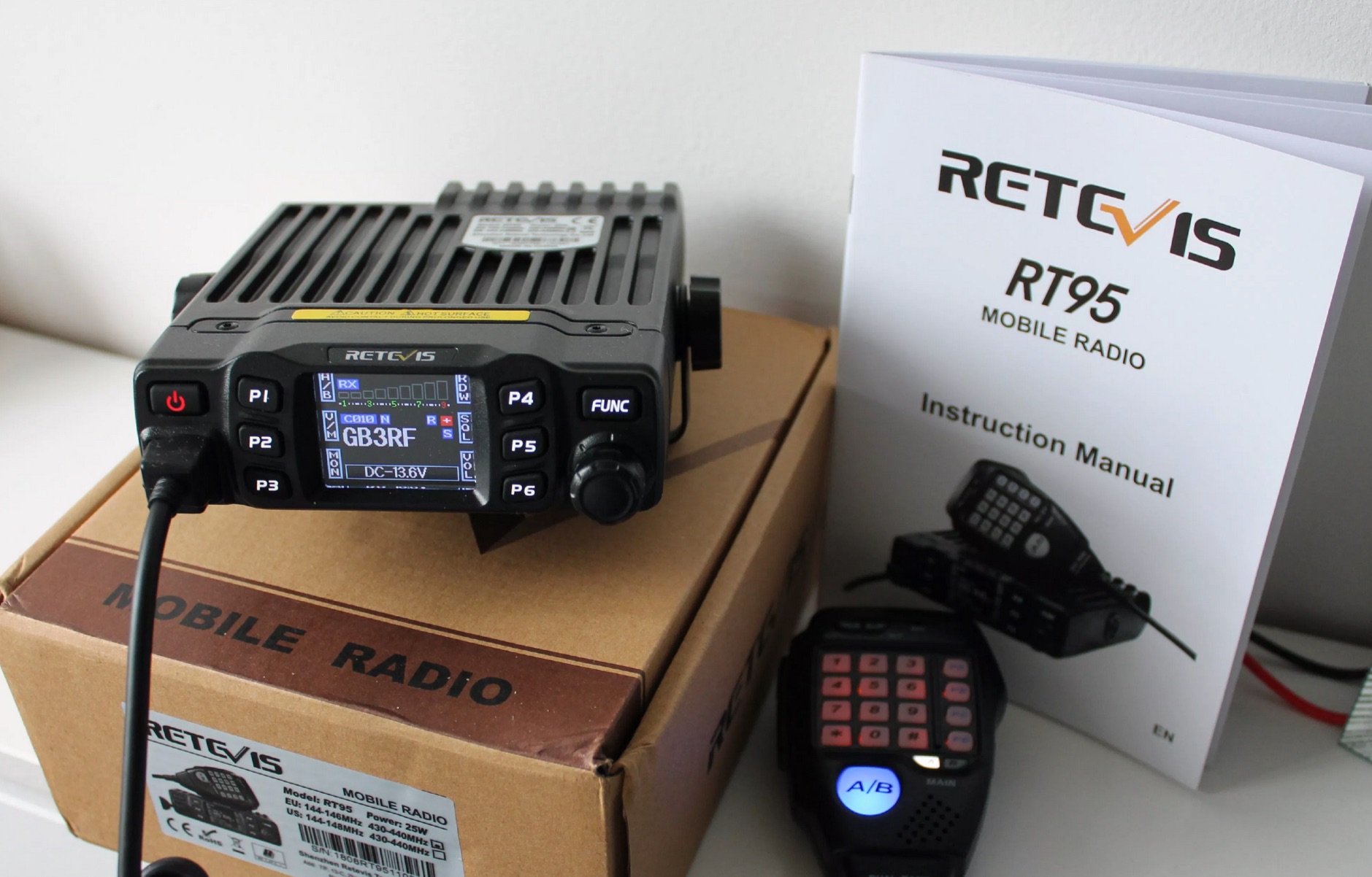 Review of the Retevis RT95 also marketed as Anytone AT-778UV dual band VHF UHF FM mobile radio transceiver
 -
 The BTech DMR-6X2 dual-band DMR handheld radio is thoroughly reviewed, detailing its features and performance for amateur radio operators. This resource covers the radio's capabilities for both VHF and UHF frequencies, supporting Tier II DMR digital and FM analog modes. It highlights key specifications such as its **136-174 MHz** and **400-480 MHz** frequency ranges, CTCSS/DCS, DTMF, 2-TONE, and 5-TONE signaling, and its _digital simplex repeater_ function. The review provides a comprehensive unboxing experience, listing included accessories like two Li-Ion batteries (2100 and 3100 mAh), a programming cable, and a 37-page English user guide. It also specifies the radio's physical dimensions of 5.1 x 2.4 x 1.5 inches and weights of 9.9 oz with the 2100 mAh battery and 10.8 oz with the 3100 mAh battery, offering practical insights for hams considering this transceiver.
 -
 Documents the construction of a **VHF/UHF** antenna addition for the Buddipole HF antenna system, leveraging the existing Versa-Tee component. The project details the fabrication of a custom antenna mount from angle aluminum, including specific drilling and tapping for 3/16"-24 bolts, and the creation of radials from Simpson Strong Tie Insulation Supports. It specifies radial lengths for 70 centimeters (6 inches from the center stud) and 2 meters (19 1/4 inches), noting the use of wire nuts for safety. The resource outlines the construction of a mast from 1/2" ID PVC conduit, connected with 3/8"-24 connecting nuts and bolts, mirroring the Buddipole's modular design. It describes the integration of a mobile dual-band antenna with a 3/8"-24 mounting stud and the custom coax setup with BNC and **PL-259** connectors. Field testing with an FT-817ND and a separate dual-band SWR meter confirmed good SWR on both 2 meters and the 440-450 MHz section of 70 centimeters, with positive reception reports during Field Day activities. Further, the article describes the creation of a custom carrying solution, including a 22-inch tripod bag and a fabric roll-up, to emulate the portability of the original Buddipole system.
 -
 The CQ World Wide DX Contest records document top scores, with the Multi-Multi SSB category showing CN8WW achieving **78,170,508 points** in 2000. These records span from 1948 to 2025, categorizing results by region, operating class (e.g., Single Operator High Power, Low Power, QRP, Assisted), and specific bands like 10M, 15M, 20M, 40M, 80M, and 160M. For instance, EF8R (E77DX) holds the All-Band High Power SSB record with **25,747,775 points** in 2025. Each entry includes the callsign (with operator callsign in parentheses for guest ops), year of operation, and total score. The _CQ WW DX Contest_ also features records for the RTTY and VHF contests, alongside the main SSB and CW categories. QRP records demonstrate significant achievements, such as P40W (W2GD) with 5,097,780 points in the All-Band SSB QRP category in 2000. Multi-Two and Multi-Single categories are also detailed, providing a comprehensive overview of competitive performance.
 -
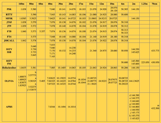 A summary of common calling frequency for each digital mode on that band.
 -
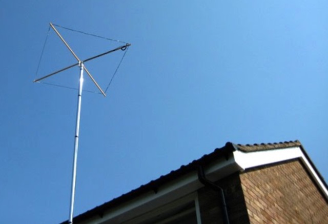 The Homebase-10 is a wire halo antenna for 10m built with DIY store parts, effective despite its small size. Includes a dual-band version for 10m and 6m with gain around 0 to -2dBd, near omnidirectional pattern, and horizontal polarization. Overview based on a 2008 Practical Wireless article.
 -
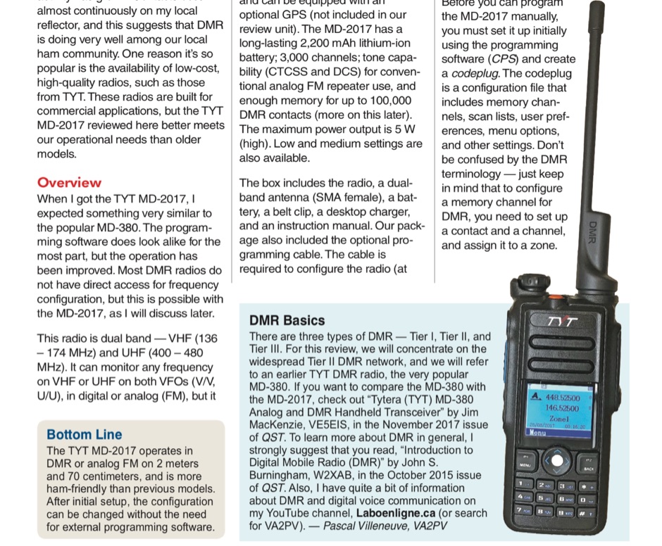 TYT MD-2017 Dual-Band Analog and DMR Handheld Transceiver Reviewed by Pascal Villeneuve, VA2PV
 -
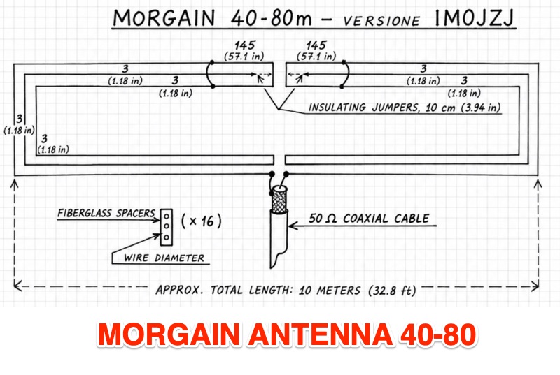 Presents the construction of a shortened _Morgain_ dual-band wire antenna for 40 and 80 meters, specifically designed for installations with limited physical space. The design achieves a compact footprint of approximately 10 x 0.5 meters, utilizing 64 meters of 1.5 mm² insulated electrical wire. The article details an alternative configuration that reduces the antenna's physical length while maintaining its electrical characteristics for dual-band operation. Author _Remo - IM0JZJ_ conducted tests from Sant'Antioco, Sardinia, reporting SWR measurements of 1.2:1 to 1.4:1 on 40 meters. On 80 meters, SWR ranged from 1.1:1 to 1.5:1 across 3620 kHz to 3720 kHz, with a 1:1 current balun recommended for coaxial feed due to the antenna's approximately 50-ohm feed-point impedance. The installation used two 11.50-meter galvanized steel poles, supporting the antenna at about 10 meters above ground. Construction involves three wooden boards and sixteen fiberglass laminate spacers, with specific instructions for routing the 32-meter wire arms. The design eliminates jumpers for 40-meter tuning but requires two jumpers approximately 1.45 meters from the ends for 80-meter operation, which are tuned and then permanently soldered.
 -
 High power, UHF, L-band, S-band, C-band, microwave frequency amplifier and oscillator devices, pulsed, CW, fixed-tuned, or tunable devices in the range of 600 MHz to 2000 MHz
 -
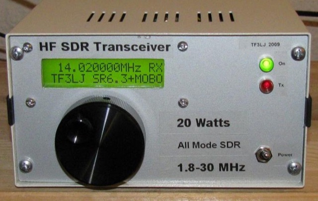 This project describes a DIY all band HF SDR transceiver. Built around a Softrock 6.3 kit, it boasts a 20W homebrew amplifier and ATmega168 microcontroller for USB control. An LCD displays frequency, power, and SWR. Automatic LPF selection and SWR protection enhance functionality. Compatible with Rocky and PowerSDR software, this project provides a cost-effective and powerful HF SDR transceiver for hobbyists.
 -
 The Tri-pole antenna, a clever modification of a standard dipole, allows for dual-band operation by integrating a third element. This design effectively shortens the overall dipole length by 10 to 20 percent, simplifying antenna rotation and offering a compact footprint. KK4OBI's article delves into the operational principles, using a 6 and 10-meter Tri-pole as a primary example, and provides comprehensive instructions for constructing any Tri-pole antenna within the 6 to 15-meter range. Key to the Tri-pole's performance is its off-center feed, necessitating a common mode choke at the feed point for optimal tuning and reduced noise. The author outlines a methodical approach to determining element dimensions, starting with a vertical element frequency calculated as 0.47 times the sum of the desired upper and lower band frequencies. This calculation, along with K-values derived from trend lines, guides the initial lengths for the horizontal arms, demonstrating how a 10m-6m Tri-pole can achieve a total horizontal length 78% shorter than a conventional 10-meter dipole. Tuning and balancing are critical, with the article detailing adjustments to arm lengths and the vertical element to achieve balanced SWR values, as validated through 4NEC2 simulations. Radiation patterns are analyzed at various elevations, showing gains around 5.7 dBi and favorable take-off angles for DX contacts. Construction details specify aluminum tubing dimensions, U-bolts, and an SO-239 connector, emphasizing the importance of a ferrite-based choke for wideband operation.
 -
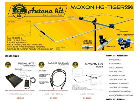 One of the featured products, the V350 CAMP, is a multiband vertical antenna covering 6 to 80 meters, priced at R$ 799,90, demonstrating the range of ready-to-use solutions available. The inventory includes various antenna types such as **HF**, **VHF**, and **UHF** designs, along with dual-band options like the J-Pole Dual V/UHF for R$ 235,00. For those building their own arrays, the store stocks essential components like element holders, clamps, junction boxes, and aluminum plates, alongside specialized items such as the KIT Isolador Central Dipolo - 01DX for R$ 99,90. The shop also provides a comprehensive selection of installation hardware, including diverse antenna mounts, PTT supports, and various coaxial cables like RG58 and RG213, with prices up to R$ 849,90 for RG213. Connectors such as UHF male PL259 and various adapters are readily available, ensuring compatibility for different setups. Additionally, specialized items like side handles for popular transceivers such as the FT857/891 and IC7300 are offered, catering to specific equipment needs. Beyond antennas, the store supplies practical accessories like transport bags, 12V power cables for transceivers, and even branded merchandise like the Antena Kit mug. Rodrigo Gonçalves, PP5BT, manages the operation from Blumenau, SC, Brazil, providing direct contact via WhatsApp at +55 47 9.9985.0155.
 -
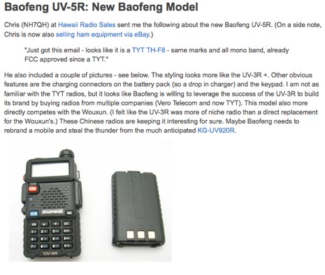 The Baofeng UV-5R handheld transceiver, introduced around 2012, operates across the 2-meter (144-148 MHz) and 70-centimeter (420-450 MHz) amateur bands, offering dual-band receive and transmit capabilities. This review provides an early assessment of the radio's form factor, user interface, and general performance, noting its compact size and the inclusion of a **VFO/Memory mode** button for frequency management. The device supports both FM and narrow FM modes, with a reported power output of 4 watts on VHF and 3 watts on UHF, making it suitable for local simplex and repeater operations. Key features discussed include its 128-channel memory capacity, a built-in VOX function, and a **DTMF keypad** for tone dialing and repeater access. The review highlights the radio's ability to scan frequencies and memories, along with a dual-watch function allowing simultaneous monitoring of two frequencies. Battery life is addressed, with the standard 1800 mAh Li-ion pack providing several hours of operation depending on transmit usage. Initial impressions cover the radio's construction and the clarity of its LCD display, which shows both A and B band frequencies.