Search results
Query: 20 m ring antennas
Links: 75 | Categories: 0
-
 This resource details the fundamental aspects of deploying longwire antennas, emphasizing ease of construction and installation for shortwave listening (SWL) and broadcast reception. It covers wire gauge selection, suggesting 14 to 24 AWG for general use, with heavier gauges (14-20 AWG) for permanent outdoor installations. Guidance is provided for various deployment scenarios, including indoor setups where the wire can be run around a room, temporary outdoor installations from balconies using light 18-24 AWG wire, and permanent outdoor configurations requiring higher placement and slack for tree movement. Feeding methods are discussed, recommending coaxial cable (50-75 ohms) to mitigate man-made interference, with instructions for connecting only the center conductor to the longwire. Safety precautions are highlighted, particularly avoiding contact with power lines and conductive materials, and managing static electricity buildup by unplugging the antenna after use and bleeding off charges before connection. The article also advises against using outdoor longwires during thunderstorms or snowstorms due to static and lightning risks. Optimal height considerations are presented, advocating for the highest safe placement, ideally a couple of feet above underlying structures, to maintain free air space. The text mentions a personal setup with one end at a roof peak (20 feet) and the other at a 17-foot mast, illustrating practical deployment without strict height requirements beyond safety and clearance.
 -
 Demonstrates the construction of **magnetic loop antennas**, detailing both multi-turn and single-turn designs. It covers a 30-inch diameter multi-turn loop for 80 meters, based on a February 1996 QST article, and an octagon single-turn loop made from 15mm copper tube with a 4.8-meter circumference, operating from 7 MHz to 14 MHz. The document also presents a smaller 800mm diameter loop for 14 MHz to 28 MHz, emphasizing the importance of high-voltage tuning capacitors. Covers the design and construction of custom **butterfly capacitors** and piston capacitors, including a split stator capacitor with 140 pF capacitance and a 6000 Volt rating, and a butterfly capacitor with 5-65 pF and 7200 Volt rating. It explains why butterfly capacitors are preferred over split stator types for high power applications due to lower losses and direct series connection of rotors, reducing resistive losses from wiper contacts. Material recommendations include clear PVC for plates and brass or stainless steel for non-magnetic hardware. Addresses practical considerations such as feeding the loop with a shielded 1/5 Faraday loop made from RG213 or RG8 coax, achieving VSWR 1.1 across bands, and optimizing its placement 180° from the capacitor. It also discusses mechanical joint resistance, dissimilar metal oxidation prevention using Vaseline, and a simple method for determining radiation angle with a TL-light tube. The guide includes diagrams for rotor, stator, and end plate construction.
 -
 The **Extended Double Zepp** (EDZ) antenna, a simple wire design, is presented as a means to achieve 3-4 dB of gain on 10 meters, with an overall length of just 43 feet. This resource, authored by WB3HUZ, details several gain antennas suitable for the 29 MHz AM segment, all modeled using EZNEC software at 30 feet above ground. Other designs include a compact rectangular loop, offering more gain than the EDZ and a lower take-off angle, and the **Lazy H**, a bidirectional antenna providing 6 dB gain, which is also workable on 20, 17, 15, and 12 meters. The Bisquare, a diamond-shaped open-top loop, is also featured, providing approximately 4 dB gain and requiring only a single support. These designs are primarily fed with ladder line or open-wire line to simplify matching, though a coax feed option for the EDZ is shown for 10-meter-only operation. The Lazy H, for instance, requires about 16 feet of open-wire line for its half-wavelength elements spaced a half-wavelength apart. An enhanced EDZ Lazy H variant is also discussed, achieving an additional 1-2 dB gain by extending element length to 1.28 wavelengths and increasing spacing to 0.64-0.75 wavelengths. The Bisquare, while primarily a 10-meter antenna, can be adapted for 20 meters by closing the top connection.
 -
 The Pfeiffer Maltese Quad Antenna System presents a unique approach to traditional quad antennas by utilizing a linear loading technique. This method effectively reduces the overall size of the antenna while maintaining its performance capabilities. Designed by Andrew Pfeiffer, the antenna's configuration resembles a Maltese cross, which not only enhances its structural integrity but also allows it to withstand challenging environmental conditions. This system is adaptable, offering various configurations from a 4-spreader Maltese Quad to a 16-spreader Maltese Quadruple-Cross, making it suitable for operators looking to optimize their setup without sacrificing efficiency. This antenna system is particularly versatile, covering multiple bands including 40, 20, 17, 12, and 10 meters. The design focuses on minimizing the physical footprint while ensuring effective signal transmission and reception. Amateur radio operators can benefit from the detailed plans available in the accompanying PDF, which outlines the construction process and specifications. Whether you're a seasoned DXer or a newcomer to the hobby, the Pfeiffer Maltese Quad Antenna System offers a practical solution for enhancing your station's capabilities.
 -
 The RXO Unitenna, a vertical wideband antenna, offers operation across the 7-21 MHz spectrum, covering the 40, 30, 20, 17, and 15-meter amateur bands. This design focuses on achieving a low SWR across a broad frequency range, making it suitable for general HF operation without requiring an external antenna tuner for minor SWR variations. The antenna utilizes a unique loading coil and matching network to maintain efficient radiation characteristics across its operational bandwidth. Construction details within the PDF document include specific dimensions for the radiating element and the counterpoise system, which is critical for vertical antenna performance. The design incorporates readily available materials, simplifying the build process for radio amateurs. Performance graphs illustrate the SWR characteristics across the 7 MHz to 21 MHz range, demonstrating the antenna's wideband capabilities. The document also provides guidance on feedline connection and grounding considerations for optimal field deployment. This vertical antenna configuration is particularly useful for hams with limited space, offering a compact footprint compared to horizontal wire antennas.
 -
 WiNRADiO Communications, a division of Radixon Group, was established in 1996 to commercialize extensive research in radio communications. The company specializes in integrating radio and computing technologies, offering a diverse product range for government, military, security, and amateur radio enthusiasts. Their product line includes the WR-G65DDCe 'EXCALIBUR Sigma' HF/VHF SDR receiver, noted for its capabilities, and the G31DDC EXCALIBUR, recognized for its price/performance ratio in shortwave listening with improved AMS and Noise Blanker features. The company also produces the G39DDC series EXCELSIOR for serious monitoring, WR-G526e/G527e/G528e modular SDR solutions for high-performance applications like phase-coherent direction finding, and the low-cost WR-G305e/G305i VHF/UHF receivers. Professional counterparts, the WR-G315e/G315i, support APCO P25 decoders and trunking options. WiNRADiO's offerings extend to the PFSL-G3 field strength logging system for mobile signal coverage, advanced multichannel telemetry systems like the MS-8323, and specialized antennas such as the AX-31C Log-Periodic and AX-81S active HF antenna. DRM decoder software is available for G3 Series receivers, enabling clear reception of DRM broadcasts. The WSS-420 Weather Satellite Receiving System and various antenna rotators are also part of their product ecosystem. WiNRADiO supports multiple operating systems, with MacRadio for Apple Macintosh users and LiNRADiO for Linux developers, providing drivers and network receiver solutions like the RLX-810.
 -
 Normal mode helix antennas for HF mobile. Photos andn plan for a 20 meters mobile helix antenna by N2MH
 -
 Demonstrates the construction and on-air performance of the _NB6Zep_ antenna, a modified 20-meter Extended Double Zepp design optimized for multi-band operation from 40 through 10 meters. The resource covers basic design principles, including dimensions of 66 feet horizontal and 5 feet vertical elements, and specifies open ladder line or TV twin lead for the transmission line. It details material selection for low-cost wire antenna construction, such as 18 AWG wire for the legs and ceramic or plastic insulators, along with practical tips for soldering connections and insulating against moisture. The author, NB6Z, shares insights from extensive _EZNEC_ modeling to optimize the antenna's total length for a 40-meter half-wave dipole footprint and feed line length for direct tuner connection. The article presents field results, including successful _PSK31_ contacts from Oregon to the East Coast on 40 and 30 meters with 50 watts, even at a low height of 6 feet. It provides detailed performance characteristics for each band, noting the _NB6Zep_'s highest gain (over 3 dB) and sharp, medium-angle lobes on 20 meters, which yielded strong DX reports to locations like Korea, Japan, and Argentina. For 17 and 15 meters, it describes a butterfly-like pattern with broad lobes, while 12 and 10 meters exhibit narrow, directional lobes in an "X" configuration. The author also shares personal experiences operating successfully for over a decade in an antenna-restricted environment using the NB6Zep and other stealth wire antennas.
 -
 Selecting an appropriate antenna system for shortwave broadcasting involves evaluating various types based on performance, cost, and operational parameters. This resource details the critical specifications for broadcast antennas, including average and peak power ratings, directivity, takeoff angle (TOA), horizontal beamwidth, and gain, emphasizing that a 100-kW transmitter requires an antenna rated for 150 kW average and 400 kW peak. It clarifies that low TOA signals travel thousands of kilometers, while high TOA is for local coverage, and nearly all modern shortwave broadcast antennas are horizontally polarized. The article explores specific antenna types, such as Log-Periodic Antennas (LPAs), which offer wide frequency ranges (e.g., 2-30 MHz) and directional patterns with 11 dBi gain, costing from $20K to over $100K for multi-curtain versions. Dipole arrays, also known as curtain antennas, are prevalent in international broadcasting, featuring steerable beams (±15° and ±30°) and mode-switching capabilities to alter TOA, with high/low pairs costing over $1 million. Fan dipoles are noted for omnidirectional patterns, smaller size, and lower cost for low-power applications, while rhombics, though simple, require resistive termination and incur several dB of I2R losses. Balun considerations are crucial, as most communications baluns are not rated for the higher average and peak powers of AM broadcast transmitters. Modern shortwave antennas utilize durable materials like Alumoweld wire rope for radiators and support elements, avoiding copper, fiberglass, or materials prone to stretching or deterioration. Feeder systems for high-power stations often require tapered-line baluns to convert 50-ohm unbalanced power to 300-ohm balanced for connection to the antenna.
 -
 What is NVIS Near Vertical Incident Skywave. This article on NVIS (Near Vertical Incidence Skywave) explores its role in short-range HF communication, covering 0-200 miles. NVIS utilizes antennas with high radiation angles and frequencies below the ionospheric critical frequency to achieve reliable local contact. He details optimal antennas, like low dipoles, and practical tips for maximizing NVIS performance, emphasizing its advantages such as reduced noise and independent operation without repeaters. However, challenges include frequency sensitivity and the need for appropriate antenna setups at both ends for effective communication.
 -
 The **NW3Z** optimized wideband antenna designs, originally presented at Dayton 2001, detail Yagi configurations for the 20-meter, 15-meter, and 10-meter amateur radio bands. This resource provides access to the design files, likely containing critical parameters such as element spacing, element lengths, and boom dimensions, which are essential for replicating these directional antennas. The designs focus on achieving wide bandwidth, a desirable characteristic for contesters and DXers operating across a significant portion of each band. The content specifically references "nw3z-Antenna-DesignsDownload," indicating that the core information is available as a downloadable file, presumably in a format suitable for antenna modeling software or direct construction. Such files typically include **NEC models** or similar data, allowing for performance analysis and optimization before physical construction. The emphasis on "optimized wideband" suggests design considerations for SWR bandwidth and gain characteristics over a broader frequency range than typical narrow-band Yagis. The resource serves as a direct source for specific, proven antenna designs from a known amateur radio antenna designer, offering practical data for hams interested in building high-performance Yagi arrays for HF.
 -
 Tarheel Antennas presents its product line of motorized **screwdriver antennas** and stainless steel mounting solutions, engineered for both amateur radio operators and commercial users. The resource details the manufacturing process, emphasizing in-house CNC machining and the use of quality materials for durability and performance. It highlights the company's commitment to U.S.-based manufacturing, with products built in St. Joseph, MO, since 2008. The site provides essential contact information for sales and technical support, including email addresses and phone numbers. It also includes a mailing address for physical correspondence. While noting a temporary absence from the Dayton Hamvention in 2024, the company expresses intent to return in 2026, indicating engagement with the amateur radio community.
 -
 End-Fed Half-Wave Antennas (EFHWAs) are analyzed for their utility in portable QRP operations, emphasizing their simplicity, efficiency, and predictable radiation patterns compared to other portable antenna types. The discussion contrasts EFHWAs with vertical antennas, random length wires, and center-fed dipoles, highlighting the common pitfalls of each, such as ground system dependency for verticals and feedline issues for dipoles. The article details the electrical half-wavelength calculation using the formula L (Ft) = 468/F(MHz) and explains how EFHWAs can be resonant on harmonic frequencies, enabling multiband operation. Various deployment configurations are presented, including the inverted L, inverted Vee, sloping wire, and vertical setups, each with specific advantages for radiation angle and polarization. For instance, a vertical EFHWA offers a low angle of radiation suitable for DX contacts without requiring an extensive ground system. The resource also addresses the counterpoise requirements, suggesting a quarter-wavelength wire or connection to a metallic structure for decoupling. A schematic diagram for a simple parallel-tuned circuit tuner, based on the _Rainbow Bridge/Tuner_ design, is provided, detailing component values for 30 and 40 meters, including a 6 microhenry toroidal inductor and a 20-100 picofarad mica compression capacitor. The tuner's adjustment process for SWR matching is also outlined.
 -
 The Buddipole website showcases a range of portable amateur radio antenna systems, including the **Buddipole**, Mini-Buddipole, Buddistick PRO, and BuddiHEX, designed for rapid deployment and multi-band operation from 40 meters to 2 meters. Each product page details specifications, operational modes (dipole or vertical), and compatible accessories like tripods, masts, and baluns. The site also features portable DC power management systems such as the PowerMini 2 and PowerPlus, which include integrated battery chargers and solar controllers, catering to off-grid or field day setups. Instructional videos demonstrate antenna assembly, tuning, and deployment techniques for various configurations, including the VersaTee vertical and Mini-Buddipole. Customer testimonials and DXpedition highlights, such as operations from Montserrat (VP2M) and Dominica (J38), provide real-world examples of the equipment's performance in challenging environments. The company, established in 2001, emphasizes modularity, versatility, and efficiency in its product line, all manufactured in the USA. Shipping information, a 30-day return policy with no restocking fee, and contact details for their Heber City, Utah facility are clearly presented. The site serves as a direct sales portal, offering a comprehensive catalog of antennas, power solutions, and components for portable amateur radio enthusiasts.
 -
 Theory, Modeling, and Practical Applications By W5JCK, presentation in PDF File. This presentation focuses on Near-Vertical Incidence Skywave (NVIS) antennas, which are crucial for short-range radio communications, particularly in military and emergency contexts. It explores NVIS theory, antenna models, and installation criteria while debunking common myths about reflectors. Key topics include usable frequency bands, optimal installation heights, and the impact of soil quality on performance. The presentation outlines the best bands for daytime and nighttime use, emphasizing the importance of understanding propagation characteristics to enhance communication effectiveness within 200 to 300 miles.
 -
 Manufacturer of Fibreglass Whip Antennas, Low and mediun Frequency, HF and VHF Antennas Specialized in the design and manufacturing of a full range of Beacon (MF), AM Broadcasting 540 - 1700 KHz, HF 1.7 to 30 MHz, VHF 30 to 156 MHz and UHF 200 to 500 MHz antennas.
 -
 JJ0DRC's HF multi-band delta loop antenna project, initially conceived during the waning peak of Cycle 23, addresses the common challenge of achieving effective DX operation from a small residential lot in Japan. Dissatisfied with a ground plane antenna's performance in SSB pile-ups, the author sought a beam-like solution without a tower, drawing inspiration from a JJ1VKL article in CQ Ham Radio Sep. 2000. The antenna, constructed in October 2000, employs two 7.2-meter fishing rods (37% carbon fiber, reinforced with cyano-acrylate glue and aluminum tape) and 1mm enameled wire, fed by an Icom AH-4 external antenna tuner. While the exact beam pattern remains unmeasured, JJ0DRC observed a significantly higher callback rate compared to dipole antennas, particularly on higher bands. The system's circumference length of 15-20m is crucial for maintaining a good beam pattern across HF bands, though performance on lower bands like 80m, 40m, and 30m becomes less directional as the length deviates from a full wavelength. Ongoing maintenance addressed degradation issues, including aluminum tape cracking and wire breakage at connection points due to strong winds (often exceeding 10-15m/s in winter). The author reinforced rod connections with IRECTOR PIPE SYSTEM components and INSU-ROCK ties, and improved wire attachment methods using Cremona rope and epoxy bond to enhance durability.
 -
 Presents a comprehensive guide for constructing a broadband Hex Beam antenna, a popular directional array for HF operation. This design offers a compact footprint and excellent gain characteristics, making it suitable for limited space installations while providing significant performance advantages over omnidirectional antennas. The resource details the specific dimensions for a five-band Hex Beam covering 20, 17, 15, 12, 10, and 6 meters, emphasizing the critical element spacing and wire lengths required for proper resonance and pattern. It outlines the construction of the center post, spreaders, and wire elements, along with the feed point assembly, ensuring proper impedance matching. The project aims for a forward gain of approximately **5.5 dBi** on most bands, with a front-to-back ratio often exceeding _20 dB_. Building this antenna requires careful measurement and assembly, but the resulting performance provides a substantial upgrade for DXing and contesting.
 -
 This project outlines the construction of a 3-element reversible quad antenna specifically designed for the 40-meter band. The materials required include pushup towers, pressure-treated posts, insulated wire, and various electrical components such as relays and a balun. The construction process is straightforward, beginning with the installation of the posts in a straight line, followed by the assembly of the antenna elements and their elevation to the desired height. The antenna's design allows for directional signal reception, making it ideal for operators looking to enhance their communication capabilities on the 40-meter band. The project includes detailed instructions on tuning the antenna for optimal performance, ensuring that operators can achieve the lowest SWR possible. Additionally, the design can be adapted for other bands by extrapolating dimensions, providing versatility for amateur radio enthusiasts. Overall, this reversible quad antenna project is suitable for both beginners and experienced operators, offering a practical solution for improving signal strength and directionality in 40-meter communications.
 -
 Demonstrates the design and construction of a 9-element Yagi antenna for the **70 cm band** (432 MHz), based on the DK7ZB concept. The resource details EZNEC+ calculations for a single antenna, providing gain, sidelobe suppression, and front-to-back ratio figures. It also presents a comprehensive analysis of stacking two such antennas, including optimal stacking distance (1000 mm) and the resulting performance enhancements for the stacked array, such as an increased gain of 17.03 dBi. The article includes detailed drawings, wire file dimensions in millimeters, and azimuth/elevation plots for both single and stacked configurations. Practical construction steps are documented with original photographs, illustrating element mounting, the **28 Ohm matching system** using two quarter-wave 75 Ohm transmission lines, and the critical N-connector wiring. It also covers the iterative process of fine-tuning the driven element length to achieve a return loss of 20 dB, validating the EZNEC+ simulation results with actual measurements.
 -
 With over 20 years of experience, Proyecto 4 operates as a specialized ham radio retailer in Madrid, Spain, providing a diverse inventory of transceivers, antennas, and related accessories. The store features popular models like the _ICOM IC-705_ and _ICOM IC-7300MK2_, alongside Yaesu transceivers such as the _FTX-1 Optima_, which delivers 100W on HF and 50W on V/UHF bands. The product range includes mobile and portable antennas, such as the D-Original DX-NR770HB, offering 3 dB gain on 144 MHz and 5.5 dB on 430 MHz, and the Diamond RH-770 with a BNC connector. CB radio enthusiasts can find the Anytone CB SMART II AM/FM transceptor and the Telecom LS145 mobile antenna, rated for 500W and 4 dB gain on 26-30 MHz. Proyecto 4 emphasizes its in-house technical service, inviting customers to visit their laboratory for repairs and technical consultations via sergio@proyecto4.com. The store also highlights customer reviews and offers promotions like Yaesu Cashback, providing savings up to 100€.
 -
 The **HFRadioSales.au** resource provides a commercial outlet for amateur and commercial radio operators seeking HF SSB equipment and related services. It focuses on the Australian market, offering new and refurbished transceivers, antennas, tuners, and a wide array of spare parts for brands like Codan, Barrett, and Qmac. The site details its role as a licensed dealer for new Barrett Communications and Codan radio and antenna systems, including specific models such as the Barrett 4050, 2050, and 950, and Codan Envoy and NGT series. This platform supports various applications, including vehicle, 4WD, outback, marine, and base station setups, catering to networks like HF Radio Club, VKS737, and RFDS. It also features commercial-grade antennas from Bushcomm, such as the BBA100C and SWC100, available for fast shipping from their Queensland warehouse. The site includes an FAQ section with general information on mobile HF communications in Australia and timelines for specific transceiver models.
 -
 GW4ALG's _136 kHz Pages_ document the evolution of vertical antennas for the 2200m band, starting with a prototype mounted on a house wall. This initial design, despite achieving the first **395 km** GM-GW QSO, suffered from significant insulation breakdown, high RF losses due to proximity to the house, and difficult tuning adjustments. The author details the challenges of maintaining resonance and matching with a variometer in the loft, noting that adding three earth spikes offered no measurable improvement over a simple water tap connection. The subsequent experimental 12m vertical, relocated away from the house, significantly reduced dielectric losses and proved far more effective. This antenna enabled GW4ALG to set a world DX record on 136 kHz with a **1916 km** QSO to OH1TN, and an intra-UK record of **703 km** to GM3YXM/P. The resource further explores the use of helium-filled balloons to extend the vertical radiator, achieving heights up to 27m, typically 20m, for enhanced low-band performance. Practical advice on balloon types, inflation, and critical insulation between the wire and balloon is provided, emphasizing safety and avoiding arcing.
 -
 The G5RV multiband HF antenna, designed by Louis Varney (G5RV) in 1946, is a popular compromise antenna offering good overall performance on most HF bands when paired with an external antenna tuner. The basic full-size G5RV measures 102 feet across the top for 80 through 10 meter operation and is fed at the center via a 34-foot low-loss feed-stub. This interaction between the radiating section and the feed-stub facilitates matching across 80-10 meters with a standard tuner, often eliminating the need for ladder line directly to the shack. The antenna's design center frequency is 14.150 MHz, configured as a 3/2-wave dipole on 20 meters, with its 102-foot length derived from long-wire antenna formulas. Construction details emphasize the matching section, which can be open wire, ladder line (window-type), or TV twin lead. Each type has a specific velocity factor (VF) affecting its physical length for an electrical half-wave on 14 MHz; for instance, open wire requires 33.7 feet (VF 0.97), ladder line 31.3 feet (VF 0.90), and TV twin lead 28.5 feet (VF 0.82). The article provides formulas for calculating these lengths and discusses the antenna's behavior on individual bands, from 3.5 MHz where it acts as a shortened dipole, to 28 MHz where it functions as two three-half-wave long-wire antennas fed in-phase. Practical construction notes include recommendations for vertical descent of the matching section, sealing the coax junction, providing strain relief, and winding a coaxial choke coil to mitigate common mode current. The resource also presents dimensions for double-size (204 ft) and half-size (51 ft) G5RV versions, along with their corresponding matching section lengths for various line types, making it a versatile reference for hams considering this classic wire antenna.
 -
 The NCDXF/IARU International Beacon Project operates a worldwide network of 18 high-frequency radio beacons, continuously transmitting on 14.100, 18.110, 21.150, 24.930, and 28.200 MHz. These beacons, initially launched in 1979 with a single station and expanded to the current 18-beacon system in 1995, provide reliable signals for both amateur and commercial users to assess current **ionospheric propagation** conditions. The system's design, construction, and operation are managed by volunteers, covering hardware and shipping costs. The resource details the evolution of the beacon network, including the transition from Kenwood TS-50s transmitters to Icom IC-7200 radios with a new controller design implemented in 2015. It explains how listening for these 100-watt signals, transmitted to vertical antennas, allows operators to determine band openings and optimal propagation paths globally. The content also references three QST articles providing historical context and technical specifics of the beacon project. Practical information includes methods for identifying transmitting beacons via a schedule or specialized software like FAROS and Skimmer, which integrates with the **Reverse Beacon Network** for automated monitoring.
 -
 The X80 multi-band HF vertical antenna, a commercial iteration of the Rybakov design, exhibits a physical length of 5.5 meters, or approximately 18 feet, and is constructed from aluminum tubing. It operates as a non-resonant vertical, requiring an external antenna tuner for impedance matching across its intended operating frequencies. The antenna's design incorporates a 1:4 UNUN at its base, facilitating a nominal 50-ohm feed point impedance for the coaxial cable. Performance observations indicate effective operation on 40 meters, 20 meters, 15 meters, and 10 meters, with reduced efficiency on 80 meters and 160 meters due to its relatively short electrical length for these lower bands. Comparative analysis with a G5RV dipole and a half-wave end-fed antenna reveals the X80 offers a lower take-off angle, beneficial for DX contacts, particularly on the higher HF bands. Field tests conducted with an Icom IC-706MKIIG transceiver and an LDG AT-100ProII autotuner demonstrate the X80's ability to achieve acceptable SWR across 80m through 10m. The antenna's compact footprint and ease of deployment make it suitable for restricted spaces or portable operations, though its performance on 80 meters is noted as a compromise compared to full-size resonant antennas.
 -
 Demonstrates various practical amateur radio projects and technical discussions through video episodes. One episode details cutting and retuning a _1/4 wave shorted stub_ from 101.7 MHz to 107.5 MHz to safeguard a transmitter's driver stage, alongside insights into advanced _160-meter antenna systems_ like eight-circle arrays and beverage antennas. Another segment covers upgrading firmware on an _ATS-20+_ receiver using AverDudes for improved display and functionality, and a detailed guide on using D-Star DR mode on an _ICOM ID-52A_ for international repeater programming. Additional content includes a deep dive into _OpenHamClock_ as a potential replacement for the HamClock project, updates on _Raspberry Pi 5_ running Trixie OS, and a review of the Choyong LC90 Internet radio with AI integration. The series also features "Ham College" episodes, which meticulously prepare viewers for the Technician Exam by covering topics such as antenna and transmission line measurements, SWR interpretation, and the functions of basic electronic components like rectifiers, relays, and transistors. Practical advice on coaxial cable characteristics, dummy loads, and proper soldering techniques is also provided.
 -
 Benelec Pty Ltd specializes in the design and manufacturing of **antennas** and RF components, covering a broad frequency range from 0.002 GHz to 8 GHz. Their product line includes Land Mobile Radio Antennas, such as HF 2-30MHz, VHF 40-180MHz, and UHF 200-520MHz models, alongside specialized Military Antennas for dismounted, UxS, C2, and EW applications. The company also produces Cellular Antennas, including 4G/5G and GPS/GNSS types, and Marine Antennas for both vessel-mounted and fixed-site installations. Additionally, Benelec offers a comprehensive range of coaxial cables, connectors like N-Type and SMA, and various radio accessories. The company's offerings extend to RF components such as duplexers, diplexers, and 50 Ohm loads, as well as DAS components like directional couplers and hybrid combiners. Benelec provides EMP and lightning protection solutions, including 1/4 Wave Stub protectors and replaceable GAS capsules. Their product catalog also features P25, DMR, and FM Analog radios, along with portable and mobile radio accessories like batteries, chargers, and cabled headsets. The company supports various sectors with robust communication solutions.
 -
 Designing and constructing portable wire antennas for HF operations, this resource explores several configurations including the _foldback dipole_ for space-constrained setups and an inductively shortened dual-band dipole for 20m and 40m. It details the calculation of inductance for shortened elements, providing a Visual Basic 6.0 program screenshot that illustrates determining coil parameters like turns and length for a **25.5 uH** inductor. The document emphasizes practical considerations such as adjusting wire lengths for optimal SWR, noting that a dual-band dipole achieved SWR below 2:1 on both 20m and 40m, with careful adjustment bringing it under 1.5:1. Further, the resource describes a half-wave antenna matched with a coaxial stub, a method often referred to as the _Fuchskreis_ in German amateur radio circles, to transform the high feedpoint impedance to 50 Ohms. This monoband solution, for a 20m application, uses a stub length of **2.98m** (0.216 lambda multiplied by coax velocity factor) and a shorted stub of approximately 48cm. The coaxial stub design is highlighted for its resilience to ground proximity, allowing it to be rolled up or laid on the ground with minimal SWR impact, making it highly suitable for portable QRP operations.
 -
 50 MHz extended 6-7 element ZX-Yagi antenna. Dimensions for the 7 elements and information on performance of a 2 stacked antennas featuring a total max gain of 20.8 dBi
 -
 An comprehensive article on 40 meters antenna comparing vertical height to the resulting gain
 -
 Valcom Guelph specializes in the design and manufacturing of a full range of MF Beacon 100 KHz - 600 KHz, AM Broadcasting 540 - 1700 KHz, HF 1.8 - 30 MHz, VHF 30 - 300 MHz and UHF 300 - 1,200 MHz and SHF up to 6 GHz antennas based in Canada
 -
 During a club's "Filetto Day" event, a comparative field test was conducted between a **Buddipole** antenna and a homemade 20/40-meter wire dipole. The author, IW5EDI, performed this personal evaluation from a mountain top at 1500 meters above sea level, utilizing a Yaesu FT-857D transceiver to switch between antennas. The observations on the 20-meter band indicated that the wire dipole consistently delivered significantly stronger signals compared to the Buddipole. Additionally, the Buddipole exhibited higher levels of **QRM** during the listening tests. The commercial Buddipole, known for its multiband capability and compact size with a self-supporting tripod, was contrasted with the simpler, larger wire dipole, which required a fiberglass fish pole for support. This direct comparison highlights practical differences in performance and deployment between a popular portable commercial antenna and a basic wire antenna in a real-world operating environment.
 -
 The Icom AH-4 autotuner operates efficiently across multiple HF bands, providing seamless automatic tuning for antennas from 3.5 MHz to 54 MHz. Its robust design allows for outdoor installation, making it suitable for field operations and fixed stations. The unit interfaces with Icom transceivers via a control cable, enabling automatic band switching and tuning. The AH-4 is capable of handling up to 120 watts of RF power, ensuring compatibility with most amateur radio setups. Its weather-resistant casing and compact form factor make it a versatile choice for operators requiring reliable performance in diverse environments. Field tests demonstrate the AH-4's ability to maintain low SWR across its operational range, enhancing signal quality and transmission efficiency. Compared to manual tuners, the AH-4 offers significant time savings and ease of use, particularly in rapidly changing band conditions. Its integration with Icom radios simplifies operation, eliminating the need for manual adjustments. The autotuner's performance is consistent with other high-end models, providing a cost-effective solution for amateur operators seeking dependable tuning capabilities without sacrificing performance.
 -
 The **TransWorld Antennas TW2010 Traveler HF Portable Vertical Antenna** assembly video provides a visual walkthrough for deploying this popular portable HF antenna. It details the step-by-step process, from unpacking components to final setup, which is crucial for operators preparing for field day operations or DXpeditions. The video focuses on practical aspects, showing how to connect the various elements and secure the antenna for optimal performance. Operators often seek clear assembly instructions for portable antennas like the TW2010 to ensure quick and correct deployment in diverse environments. This visual aid helps clarify potential ambiguities found in written manuals, illustrating the proper handling of the antenna's radial system and telescopic elements. The video serves as a valuable resource for those aiming to achieve efficient operation with the **TW2010 Traveler** in a portable setting. Understanding the assembly sequence can significantly reduce setup time and prevent common errors encountered during initial deployments.
 -
 A presentation of the Yagi Antennas, and other interesting tid-bits by Brian Mileshosky. The document provides an in-depth exploration of the Yagi-Uda antenna, detailing its historical development, design principles, and performance characteristics. Originally described in the 1920s, the Yagi antenna features a driven element and parasitic elements, including reflectors and directors, which collectively determine its behavior. The document highlights how element lengths, diameters, and spacing influence gain, impedance, and directivity. It also discusses the antenna's reciprocal nature and presents data on typical gain values for various element configurations. Additionally, the text covers practical considerations, such as the construction of a "Tape Measure Yagi" for amateur use, and touches on related antenna types like dipoles and their application in Near Vertical Incident Skywave (NVIS) communication.
 -
 A 7 dB directional gain is reported for this portable VHF Yagi antenna design, which utilizes cut metal tape measure sections for its elements. The resource details the construction process for a 2-meter band antenna, emphasizing its ease of build and portability. It specifically mentions the design's suitability for radio direction finding (RDF), fox hunting, and communication with satellites and the International Space Station (ISS), highlighting its practical applications for amateur radio operators. The construction cost is estimated at under $20, with potential for even lower expense if salvaged materials like old tape measures and PVC pipes are used. The article references _Joe Leggio's_ (WB2HOL) original design, noting specific alterations made by the author. It also compares this design to other DIY Yagi antennas, including _FN64's_ 2-meter band and _manuka's_ 70-cm band tape measure Yagis, underscoring its unique combination of simplicity, portability, and effective performance with a 1:1 SWR achievable on the 2-meter band.
 -
 Tuning non-resonant antennas and usage of such technique during contests.
 -
 IZ5CML, Enrico Giannerini, obtained his amateur radio license in 1998, achieving DXCC contacts with all entities over 18 years of activity. His station, located in Empoli, Tuscany, Italy, focuses on HF and 50 MHz operations, primarily using SSB, CW, and some RTTY. He emphasizes direct radio communication, preferring "human modes" over digital modes like FT8/4, which he views as detaching the operator from the signal. Enrico's operating interests include DXing, IOTA activations, and major HF contests, where he has participated both individually and with teams like IQ5LV and IO5O. Notable activations include Sao Miguel and Flores (CU8, EU-089) in the Azores in 2005, and Antiparos and Paros (EU-067) in Greece in 2006 and 2014. He also contributes to the Hamradioweb forum, promoting good operating practices and publishing the monthly "Dxschedule" for upcoming DX and contest activities. The website includes a blog with articles on DX, ionospheric propagation, and antennas, reflecting his long-standing passion for radio, sparked by the 1980s film "La Tenda Rossa" and years as an SWL.
 -
 Antenna Authority Inc. offers a wide assortment of directional, wideband antennas and other equipment specifically engineered for radio direction finding (DFing) and geolocation applications. Their product line includes _log periodic_, _cavity-backed spirals_, and _Yagi_ antennas, alongside covert antenna solutions for various operational requirements. The company emphasizes its expertise in designing and manufacturing specialized antennas for both overt and covert operations. Beyond standard offerings, Antenna Authority Inc. provides custom design services to meet specific client needs, focusing on tailored RF directional products. Their capabilities extend to developing antennas for vehicles and optimizing their operational performance in diverse scenarios. The firm is located at 3381 W. County Line Road, Douglasville, Ga. 30135-1145. Ferrel Bentley is associated with Antenna Authority Inc., which has been operating since at least 2005, as indicated by the copyright notice.
 -
 Main High Frequency Antennas from the 2009 LARC FARL Field Day, Ford Amateur Radio League. A document comparing antenna performances and flexibility among a G5RV an Carolina Windom and a Cushcraft R7 vertical antenna.
 -
 Presents field test results for an **elevated SuperAntenna MP-1** portable antenna, configured on a tripod for HF operations. The resource details the antenna's setup and performance during a portable activation, focusing on its use across the 40-meter, 20-meter, and 17-meter amateur bands. It includes observations on signal reports and operational considerations for this specific portable antenna configuration. The content provides practical insights into deploying the MP-1 antenna in a non-ground-mounted setup, which is often a point of interest for portable and QRP operators. It documents the author's experience with the antenna's tuning and effectiveness for making contacts under real-world conditions, offering a user-perspective review of its capabilities. The article also features photographic evidence of the antenna's deployment, illustrating the tripod mounting and the overall portable station setup.
 -
 Designing and constructing a two-element receiving loop antenna array for HF operation involves specific considerations for achieving high directivity and noise reduction. This resource details a homebrew system comprising two 30-inch diamond-shaped loops, spaced 20 feet apart, which are fed through mast-mounted preamplifiers and passive signal combiners. The operational principle relies on adjusting phase delays between elements via precise _Belden 8241_ coaxial cable lengths, optimized for specific bands from 160m to 20m. Performance data, derived from _EZ-NEC_ modeling, illustrates consistent 90° azimuth-plane beamwidth and low take-off angles across the target bands, with _Receiving Directivity Factor_ (RDF) values comparable to a 300-foot Beverage antenna. The article presents detailed elevation and azimuth plots for 20m, 30m, 40m, 80m, and 160m, demonstrating the array's ability to provide strong response at low DX angles while also supporting _NVIS_ signals. Key components like the _DX Engineering RPA-1_ preamplifier and _DXE RSC-2_ signal combiner are discussed, alongside the importance of impedance matching to preserve antenna patterns. The construction emphasizes self-contained elements that do not require ground radials, offering a compact solution suitable for suburban environments and stealth installations, with a focus on optimizing receive performance independently from transmit antennas.
 -
 Over 150 pages of content are dedicated to maximizing activity on the 6-meter band, often referred to as the _Magic Band_. The resource details various propagation modes, including sporadic E, F2, and tropospheric ducting, providing insights into their characteristics and how to leverage them for DX contacts. It also covers essential equipment considerations, from transceivers and transverters to specific antenna designs optimized for 50 MHz operation, such as Yagis and Moxon antennas. The eBook presents strategies for participating in 6-meter contests and pursuing awards like _VUCC_, offering practical advice on logging software and operating techniques. It includes discussions on software tools useful for predicting propagation and managing contacts, alongside guidance on finding and utilizing DX maps to identify openings. The author, K5ND, shares his extensive experience to help operators achieve successful 6-meter DXing. Specific sections address the code of practice for 50 MHz operations and provide assistance in locating rare DX opportunities. The content is structured to guide both new and experienced operators through the nuances of the band, from initial setup to advanced operating strategies.
 -
 A portable operation experience with a SpiderBeam pole during a contest, testing wire antennas, like dipole and delta loops configurations on 20 40 and 80 meters band.
 -
 High Speed Multimedia (HSMM) radio, as introduced by John Champa, K8OCL, represents a significant advancement in amateur radio's digital capabilities, moving beyond traditional keyboard modes like packet radio. This initiative, driven by ARRL's Technology Task Force, focuses on developing high-speed digital radio networks capable of up to 20 megabits per second. HSMM primarily facilitates digital voice (DV) and digital video (ADV), enabling real-time video transmission from emergency scenes to an EOC without expensive ATV gear, often requiring only a laptop, a PCMCIA card, a digital camera, and a small antenna. The working group's initial efforts concentrate on cultivating microwave skills within the amateur community to build and support portable and fixed high-speed radio-based local networking, or **RLANs**. These networks prove invaluable for RACES and ARES organizations, as well as homeland security and other emergency communications. Field Day exercises and simulated emergency tests (SETs) are encouraged to hone skills in rapid site surveys and deploying broadband HSMM microwave radio networks, with examples like linking Field Day logging stations or antenna test results at the Midwest VHF-UHF Society Picnic 2003. Getting started with HSMM often involves adapting off-the-shelf **IEEE 802.11** (WiFi) equipment to comply with amateur radio regulations, typically operating in the 2.4 GHz ISM bands. While consumer WiFi gear has range limitations under Part 15 rules, proper setup under amateur regulations can extend coverage significantly, with test networks like the Hinternet achieving 5-15 mile ranges at 54 M bit/s using small mast-mounted dish antennas. Careful selection of equipment with external antenna ports, high transmit power, and low receive sensitivity is crucial, along with using low-loss coaxial cable like LMR-400 for optimal performance at these frequencies.
 -
 The "DIY Telescopic-V Antenna £35" project showcases the creation of a budget-friendly, portable telescopic V-shaped antenna inspired by commercial designs. Using eBay-sourced telescopic whips and custom mounting solutions, the author documents their process, testing, and adaptations. Despite challenges like weather and missing tools, the antenna performed well across multiple bands, enabling successful QSOs. Future improvements include exploring loading coils and testing in better locations. The compact design offers versatility for amateur radio enthusiasts seeking an affordable and practical solution.
 -
 The PAC-12 Antenna, a multi-band portable vertical, is meticulously detailed in this construction article by James Bennett, _KA5DVS_. The design emphasizes ease of homebrewing using readily available components from local hardware stores, including replaceable loading coils. It outlines the preparation of the 72-inch telescoping whip (originally from Radio Shack, with an alternate source now provided by _Pacific Antenna_), the construction of the loading coils from PVC risers, and the fabrication of the aluminum rod base sections. Specific instructions cover threading aluminum rod with a _1/4-20 threading die_ and assembling the feedpoint insulator with a BNC connector, along with recommendations for radial deployment. KA5DVS, an avid traveler and QRP enthusiast, developed the PAC-12 to address the bulkiness of random wire setups and the limitations of commercial portable antennas like the Outbacker or SuperAntennas MP1. His goal was a lightweight, packable antenna that disassembles into 12-inch sections, achieving an assembled length of approximately 8 feet. The design strategically places the loading coil away from the base for improved efficiency. The PAC-12 notably placed first in efficiency compared to a quarter-wavelength wire vertical at the HFPack antenna shootout during the Pacificon conference in October 2001, demonstrating its practical performance for field operations. Appendix C showcases various _NJQRP Club_ members' PAC-12 constructions, including a 20m beam made with multiple PAC-12 elements.
 -
 Operating as FY/F5UII, Christian F5UII conducted a DXpedition to French Guiana (FY) from January 13 to 30, 2013. The primary operation utilized the FY5KE radio club station in Kourou, with activity focused on voice modes during specific weekday hours. The resource details the operator's intent to transmit before 12:00z and after 22:00z, or as availability permitted, from the mainland. A significant aspect of this operation involved a dedicated weekend activation of the Salut Islands, specifically **IOTA SA-020**, from January 19-20, 2013. This segment of the DXpedition was conducted from Royal Island (Ile Royale), part of a group including Devil's Island (Ile du Diable) and St. Joseph Island (Ile Saint Joseph), located 14 km offshore from Kourou. The station setup for the IOTA activation included 100 Watts of power, a GPA-030 vertical antenna for 10m, 15m, and 20m, and dipole antennas for 17m and 40m, with antenna deployment contingent on site conditions and propagation. The operator anticipated strong interest for the SA-020 entity.
 -
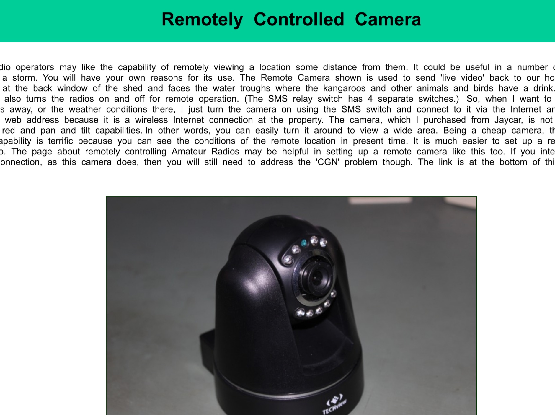 Remote viewing can be useful for Hams, in example remotely viewing antennas during a storm.