Search results
Query: 27 meters
Links: 20 | Categories: 0
-
 The ZS6BKW multiband HF antenna, a design by ZS6BKW (G0GSF), functions effectively on multiple HF bands without requiring an Antenna Tuning Unit (ATU) for 40, 20, 17, 12, 10, and 6 meters. This antenna, approximately **27.51 meters** (90 feet) long with a 12.2-meter (40-foot) open-wire feeder, is a direct descendant of the _G5RV_ but offers superior multi-band resonance. It can be deployed as a horizontal dipole or an inverted-vee, with the latter requiring only a single support and maintaining an apex angle of at least 90 degrees to prevent signal cancellation. Performance data, recorded with an MFJ Antenna Analyser, indicates SWR values of 1:1 on 7.00 MHz (40m) and 14.06 MHz (20m), with SWR below 1.3:1 on 17m, 10m, and 6m. While primarily designed for these bands, the antenna can be adapted for 80m, 30m, and 15m with an ATU, preferably at the balanced feeder's base. The use of 450-ohm twin-lead for the feeder is recommended over 300-ohm for improved strength and reduced losses, especially in adverse weather conditions. This design, originally published in _RadCom_ in 1993 and featured in Pat Hawker’s "Antenna Topics," provides a compact and efficient solution for HF operation, particularly for those with limited space or resources.
 -
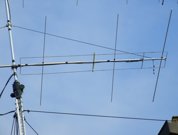
 A rotary trapped-dipole for 17 and 20 meters, as described by IZ7ATH, presents a practical solution for multi-band HF operation. The author, Talino, recounts his experience building this antenna for IK7ZCQ, detailing the evolution from an initial concept involving a grounded-driven element and gamma-match to a direct-fed, non-grounded design. His pragmatic approach, adapting available materials, is evident throughout the construction narrative, particularly with the use of eight tapered aluminum pipes for the driven element. Construction specifics include precise measurements for the aluminum tubing, with diameters ranging from 30 mm down to 16 mm, and a critical note on reducing tip thickness for weight optimization. The _traps_, initially a concern, are fabricated using 8 turns of RG58 coax on a 27 mm support, tuned to resonate at 18.1 MHz using a dip-meter. Talino emphasizes sealing the traps with RF glue and PVC tape to prevent water ingress, a crucial step for longevity. Field test results, conducted on a 10-meter pole in a clear garden environment, showed an SWR of 1.2:1 on 17 meters and 1.5:1 at 14.200 MHz. While SWR varied slightly when installed at Mario's QTH due to nearby objects, the antenna's performance remained commendable. The final half-dipole length is 46 cm for the 18 MHz tips, and the total weight is under 6 kg, with potential for further reduction.
 -
 AM/FM/CW QRP RF Power Amplifier for the HF 10 or 11 meterband (28MHz/27MHz)
 -
 This resource details the computer-optimized design of the _ZS6BKW_ multiband dipole, an evolution of the classic _G5RV_ antenna. It begins by referencing the original 1958 RSGB Bulletin article by Louis Varney G5RV, explaining the operational principles of the G5RV's flat-top and open-wire feedline on 20m and 40m, noting its impedance transformation characteristics for valve amplifiers of that era. The article then transitions to the rationale for optimizing the design for contemporary solid-state transceivers requiring a 50 Ohm match. The core of the project involves using computer modeling to determine optimal lengths for the flat-top and matching section, aiming for a VSWR of less than 2:1 on multiple HF bands. It discusses the process of calculating feedpoint impedance based on antenna length and frequency, referencing professional literature from Professor R.W.P. King at Harvard University. The analysis also considers the characteristic impedance (Z(O)) of the open-wire line, identifying a broad peak of adequate values between 275 and 400 Ohms. Specific design parameters for the improved ZS6BKW are presented, including a shorter flat-top and a longer matching section compared to the original G5RV, with a velocity factor of 0.85 for the 300 Ohm tape. The article confirms acceptable matches on 7, 14, 18, 24, and 28 MHz bands when erected horizontally at 13m, and also discusses performance in an inverted-V configuration, noting frequency shifts. The author, Brian Austin ZS6BKW, emphasizes the antenna's suitability for modern 50 Ohm coaxial cable without a balun.
 -
 This resource details the construction of a versatile CW/QRSS beacon, designed around a Microchip _PIC16F84_ microcontroller. The project provides a flexible platform for transmitting either standard CW or very slow QRSS signals, making it suitable for LF, VHF, UHF, and SHF applications. It supports two distinct messages, each configurable for speed (from 0 to **127** WPM for CW, or up to **127** seconds per dot for QRSS) and repetition within a six-phase sequence. The core functionality relies on the PIC's EEPROM, which stores all operational parameters, including message content, transmission speeds, phase configurations, and relay control settings. This design allows for parameter modification directly via programming software like _ICProg_ without altering the main program code. The project includes a detailed schematic, a component list, and an explanation of the EEPROM memory mapping for messages, speeds, phase settings, and inter-phase delays. General-purpose outputs (OUT1, OUT2, OUT3) provide dry relay contacts for external control, enabling functions such as power switching, antenna selection, or frequency changes. A 'TRIGGER' input facilitates controlled starts or continuous free-run operation. Sample EEPROM configurations illustrate how to program specific beacon sequences, including message content and relay states.
 -
 Tuning the Solarcon Antron A-99 antenna for 20 meters band
 -
 Presents the DBO274 Citizen Band mailbox, a digital communication hub accessible via HTTP and Telnet, specifically catering to **CB radio** enthusiasts in Germany. This resource outlines its functionality for Packet and other digital emissions on the 11-meter band, a segment often overlooked by traditional amateur radio operators but vital for CB users seeking advanced communication methods. The author, DH8YMB, provides insights into its operation, reflecting practical experience with digital modes in the CB spectrum. The DBO274 serves as a bridge, enabling users to exchange messages and data packets, extending the reach and utility of standard CB transceivers. It represents a localized digital infrastructure, demonstrating how the 27 MHz band can support more than just voice contacts, incorporating elements of early internet-like communication within the CB community. This setup highlights the enduring innovation within the CB realm, adapting technologies like Packet Radio for a different user base. It underscores the versatility of radio communication, even on less conventional bands, for those interested in digital data exchange beyond the typical amateur allocations.
 -
 A 27-28 Mhz quad loop antenna by Bernard Mourot F6BCU in french
 -
 Presents a QRP AM/CW transmitter project specifically designed for the 10-meter band, utilizing a crystal oscillator and a collector-modulated AM oscillator. The design employs a 2N2219(A) transistor in a Colpitts configuration, generating 100 to 350 mW of RF output power depending on the 9-18 Volt supply voltage and modulation depth. Frequency stability is maintained by a 28 MHz crystal, with fine-tuning possible via a Ct1 trimmer capacitor for approximately 1 kHz adjustment. The resource details the RF oscillator stage, implemented with a 2N2219 NPN transistor, emphasizing frequency stability and low power dissipation. It also covers the amplitude modulation stage, managed by a 2N2905 PNP transistor, which impresses audio information onto the carrier. Selective components (C3, C4, C7, C5) enhance voice frequencies within a +/- 5 kHz bandwidth, and modulation depth is controlled by R2 and R3. The project includes a 3-element L-type narrow bandpass filter (Ct3, L3, C10) to suppress harmonics and ensure a clean output signal. The project provides a complete schematic diagram, a comprehensive parts list including specific capacitor, resistor, and inductor values, and construction notes for the coils (L1, L2, L3). It also offers practical advice on enclosure requirements, suggesting an all-metal case or a PVC box with graphite paint for RF shielding. Operational parameters such as current draw (27mA@9V to 45mA@16V) and input impedance (50 Ohms) are specified, alongside guidance on antenna matching and the importance of a valid amateur radio license for 10-meter band operation.
 -
 The grounded half loop describe in this article is basically a half wave length wire on 80 Meters. The 80M grounded half loop antenna, inspired by a 1984 QST article by SM0AQW, is a compact solution for limited spaces. Comprising a 127-foot wire fed against ground and supported by radials, it balances performance and practicality. Despite compromises in length and proximity to structures, the antenna delivers strong signal reports and effective multi-band tuning using an SGC 237 antenna coupler. Ideal for CW operation, it offers low SWR on 80-10M, though noise levels and safety considerations warrant attention. This versatile design excels in constrained environments.
 -
 The Yaesu VX-5R, manufactured between 199x and 200x, offers a transmit frequency range covering 50-52 MHz, 144-146 MHz, and 430-440 MHz for European models, with US versions extending to 50-54 MHz, 144-148 MHz, and 430-450 MHz. Its receiver boasts an impressive wideband capability from 0.5 MHz to 999 MHz, with cellular frequencies blocked in some regions. The unit provides up to 5 watts RF output on 6 meters and 2 meters, and 4.5 watts on 70 centimeters, with selectable lower power settings down to 300 mW. This handheld transceiver utilizes a double conversion superheterodyne receiver system, featuring a 47.25 MHz first IF for FM and 45.8 MHz for WFM. Key specifications include a frequency stability of ±5 ppm across a wide temperature range and a current drain of 25-150 mA on receive. The VX-5R supports 220 regular memory channels with alpha tags, 3 home channels, and 10 NOAA weather channels, all stored in non-volatile EEPROM. Additional features include CTCSS/PL and DCS with tone search, ARS, ARTS, an internal voltmeter, and a Spectra-Scope. The device operates on a 7.2 VDC battery pack or 10-16 VDC external power, weighing 255 grams with dimensions of 58x88x27 mm. The VX-5R was also available as the metallic silver VX-5RS.
 -
 The Receiver Test Data resource is a detailed review database focusing on the performance metrics of various radio receivers. The methodology involves rigorous lab measurements, often adhering to standards such as the ARRL RMDR (Reciprocal Mixing Dynamic Range) and BDR (Blocking Dynamic Range). Specific test equipment and protocols are utilized to assess parameters like noise floor (dBm), AGC threshold (uV), and LO noise (dBc/Hz). For example, the _Icom IC-7300_ is evaluated with a noise floor of **-133 dBm** and an LO noise of **-141 dBc/Hz**, providing insights into its performance under different operational conditions. The resource includes a wide range of models, from the _Elecraft K3S_ to the _Yaesu FTdx-101D_, each tested for dynamic range, sensitivity, and selectivity. The data is sorted by key metrics such as third-order dynamic range and phase noise limitations, with RMDR values calculated by subtracting 27 dB from LO noise figures. This structured approach allows users to compare different receivers' capabilities, focusing on technical specifications and performance outcomes in various scenarios. DXZone Focus: Review Database | Lab Measurements | -133 dBm | ARRL RMDR
 -
 The NB6Zep Antenna, an electrically shortened 80-meter end-fed wire, addresses space constraints for low-band operation by integrating two loading coils into a 37-foot wire. This design, modeled with _EZNEC_, explores configurations like the quarter-wave sloper and inverted-L, with the latter providing a more vertical radiation pattern and practical backyard deployment. The resource details specific coil construction, recommending 21 uH coils made from _BW coil stock #3026_ or similar, and outlines wire segment lengths for optimal tuning. Performance analysis indicates a radiating efficiency of approximately 27% with good ground conductivity, resulting in a signal typically 3-4 dB down compared to a full-size quarter-wave vertical. The antenna exhibits a narrow bandwidth, around 50 kHz, due to its high Q, necessitating a tuner for broader band operation. Feedpoint impedance is low, with ground resistance playing a critical role in achieving a usable SWR. The article emphasizes the importance of an effective ground rod at the feedpoint for proper operation and tuning, suggesting an antenna analyzer for precise adjustments. It confirms the antenna's suitability for DX, citing successful contacts from Oregon to the East Coast and Hawaii on a 160-meter variant, making it a viable option for urban operators seeking low-angle radiation on 80 meters.
 -
 The 160-meter amateur radio band, spanning 1.8 to 2 MHz, was historically the lowest frequency amateur allocation until the introduction of the 630-meter and 2200-meter bands. ITU Region 1 allocates 1.81–2 MHz, while other regions use 1.8–2 MHz. This band, often called "Top Band" or "Gentleman's Band," was established by the International Radiotelegraph Conference in Washington, D.C., on October 4, 1927, with an initial allocation of 1.715–2 MHz. Effective operation on 160 meters presents significant challenges due to the large antenna sizes required; a quarter-wavelength monopole is over 130 feet, and horizontal dipoles need similar heights. Propagation is typically local during the day, but long-distance contacts are common at night, especially around sunrise and sunset, and during solar minimums. The band experienced a resurgence after the LORAN-A system was phased out in North America in December 1980, leading to the removal of power restrictions.
 -
 A Yagi-Mag antenna for the 4 meters band with NEC and MMANA files plans and pictures
 -
 Presents a historical timeline of amateur radio satellites, beginning with the inaugural _OSCAR 1_ in 1961 and extending through ARISSat-1 in 2011. It outlines the evolution of these orbiting transponders, initially simple battery-operated beacons, into sophisticated platforms supporting educational initiatives, emergency communications, and technology demonstrations. The document highlights the significant contributions of various AMSAT organizations and other entities in developing and deploying these spacecraft. Each entry provides specific launch details, including the date, launch vehicle, and initial orbital parameters such as apogee, perigee, and inclination. For instance, AMSAT-OSCAR 7 (AO-7) launched in 1974 into a 1459.00 x 1440.00 Km orbit, while AMSAT-OSCAR 40 (AO-40) achieved a highly elliptical 58665.00 x 1157.00 Km orbit. The resource also notes the allocated amateur satellite service frequencies, including 29 MHz (10m), 145 MHz (2m), 435 MHz (70cm), 1270 MHz (24cm), and 2400 MHz (13cm). The compilation serves as a concise reference for understanding the progression of amateur satellite technology and operations over five decades, showcasing the collaborative efforts of the global amateur radio community in space communication endeavors. It details the physical characteristics and project affiliations for many of the **20** satellites listed, providing a foundational historical context.
 -
 Low-frequency (LF) radio time signals, operating primarily in the 40–80 kHz range, are broadcast by national physics laboratories for precise clock synchronization. Transmitters like **JJY** (40 kHz, 50 kW; 60 kHz, 50 kW), RTZ (50 kHz, 10 kW ERP), MSF (60 kHz, 15 kW ERP), WWVB (60 kHz, 50 kW ERP), RBU (66.66 kHz, 10 kW), and DCF77 (77.5 kHz, 50 kW) cover vast geographic areas, often several hundred to thousands of kilometers. LF signals offer distinct propagation advantages over higher-band transmissions such as GPS. Their long wavelengths (3–6 km) enable effective diffraction around obstacles like mountains and buildings. The ionosphere and ground act as a waveguide, eliminating the need for line-of-sight and allowing a single powerful station to cover extensive regions. Ground wave propagation minimizes ionospheric variability effects on transmission delay, and signals penetrate most building walls effectively. Robust and low-cost receivers, often priced at 20–30 USD/EUR, are widely used in radio clocks. These receivers typically comprise a tuned ferrite core antenna, a receiver IC (e.g., Atmel T4227, U4223B, MAS1016) for amplification and AM detection, and a microcontroller for decoding the time signal and phase-locking a local clock. Specific components for DCF77, MSF, and WWVB are readily available from vendors like HKW Elektronik and Ultralink.
 -
 Chavdar Levkov, LZ1AQ, presents an experimental comparison of small wideband magnetic loops, building on his previous work on wideband active small magnetic loop antennas. His research focuses on increasing loop sensitivity by maximizing the short-circuit current, which is directly tied to the "loop factor" M = A/L, where A is the equivalent loop area and L is its inductance. Levkov's methodology involves reducing inductance and increasing area through parallel or coplanar crossed (CC) configurations, comparing these designs against a reference single quad loop of 1 m2 area. Experimental verification included testing three distinct loop types: a simple quad loop, two coplanar crossed (CC) loops, and eight parallel loops, all designed to have a total geometric area of 1 m2. Measurements were conducted at 1.8, 3.5, 7, and 10 MHz using a small transmitter 270 meters away, with a Perseus direct sampling receiver for precise signal level assessment. The results consistently showed that CC loops, particularly Loop 5 (two CC circular loops with 1.44 m2 total area), yielded significantly higher currents, up to 9.1 dB over the reference loop at 3.5 MHz, validating M as a reliable predictor of loop sensitivity. Numerical simulations using MMANA further corroborated the experimental findings, demonstrating an almost perfect correlation between the calculated M factor and the induced loop current for 15 different loop models. Levkov concludes that CC loops offer superior sensitivity for a given loop area, while parallel loops are advantageous for minimizing physical volume. Practical recommendations suggest using loops with an M factor greater than 0.5 uA/pT for quiet rural environments, and he provides a spreadsheet tool, WLoop_calc.xls, to aid in optimizing loop configurations for specific operational needs.
 -
 The tri-band trapped delta loop antenna design operates on 80 meters (3.5–4 MHz), 40 meters (7–7.3 MHz), and 30 meters (10.1–10.15 MHz) using a single triangular wire loop. This configuration eliminates the need for an external antenna tuner or band-switching relays. The antenna's physical perimeter, approximately 270 feet, establishes 80M as the fundamental band, with specific trap placements enabling resonance on 40M and 30M. Trap design and placement are critical, with 30M traps positioned inboard of 40M traps within the horizontal element. Each slant leg measures approximately 80 feet. The resource references foundational information from the _ARRL Antenna Handbook_ and _ON4UN’s Low Band DXing_ regarding full-wave loop behavior and feedpoint impedances. The project aims to provide multi-band HF operation from a single, fixed antenna structure.
 -
 VE1ZAC's analysis details the performance of **MFJ927** and **SGC239** autotuners with portable HF vertical antennas, specifically comparing 31 ft and 43 ft configurations. The resource originated from challenges encountered during a Maritime QSO Party roving operation, necessitating a lightweight and easily deployable antenna system. Target bands for the contest included 80, 40, 20, 15, and 10 meters, with a maximum power handling of 100 W CW. The author utilized a 30-foot carbon fiber push-up pole to support a vertical wire element, noting its 2 lb weight and reliability. EZNEC modeling was employed to predict performance, showing favorable results for a 30-foot vertical with elevated radials, particularly on 40 and 20 meters. Feedpoint impedance measurements, taken with an AIM4170C, are presented for various HF bands, both with and without a 41-foot RG6 stub designed to reduce reactance on 80 and 20 meters. The stub significantly improved matching on these bands, easing the tuner's workload. Operational tests revealed issues with the MFJ927's reliability during contest setup, leading to reliance on the K3's internal tuner. The SGC239, tested post-contest, performed flawlessly. A detailed side-by-side comparison covers mechanical aspects, connection options, power bias, impedance range, board quality, and documentation. Modifications to the MFJ927, including a new aluminum case, white paint for heat reduction, and upgraded impedance-measuring resistors, are also described.