Search results
Query: cb weak
Links: 4 | Categories: 0
-
 The Kenwood TH-F6A handheld transceiver can achieve an extended transmit frequency range of 137-174 MHz, 216-235 MHz, and 410-470 MHz by removing a specific diode and chip resistor from the main PCB. This modification also expands the receive range on the A-band to 142-152 MHz, 216-235 MHz, and 420-450 MHz. For the TH-F7E, the transmit range extends to 137-174 MHz and 410-470 MHz, with a corresponding receive range on the A-band. Performing these hardware changes will reset and initialize the radio's memory contents, necessitating prior backup of important channel frequencies. Instructions are provided for constructing a homemade PC programming cable compatible with the Kenwood TH-G71A, TH-F6A, and TH-F7E. The interface utilizes an RS-232-to-logic (0-3.3V) level-shifter and a full-duplex serial connection, adapting the Kenwood PG-4S cable schematic for the TH-G71's 2.5mm and 3.5mm phono plugs. Specific schematic tweaks include changing R1 from 150 ohms to 1K ohm to optimize power from the serial port and adding a 150K ohm resistor between the Radio TXD and ground to manage the 3.3V I/O pin. Detailed plug pinouts for the 2.5mm and 3.5mm connectors are presented, with the interface's TXD connecting to the ring of the 2.5mm plug and RxD to the shield of the 3.5mm plug. Ground connects to the shield of the 2.5mm plug, while the tips of both plugs are no-connects. Debugging procedures cover verifying positive and negative power rails from the serial port, checking component polarities, and testing level-shifting and inversion functions of the interface. Software setup involves enabling "TC ON" (Menu 15 for TH-G71, Menu 9 for TH-F6) and using Kenwood's MCP programming software.
 -
 Mitigating RF noise in a mobile operating environment, particularly within a _Jeep TJ_ vehicle, presents unique challenges due to the vehicle's electrical system and chassis characteristics. This resource details practical methods for identifying and suppressing various forms of radio frequency interference (RFI) that can degrade receiver performance for both CB and amateur radio transceivers. It covers common noise sources such as ignition systems, alternators, fuel pumps, and computer modules, explaining how these components generate broadband or specific frequency noise that impacts radio communications. The guide offers actionable solutions, including proper grounding techniques, the strategic use of ferrite beads and toroids on power and data lines, and the installation of bypass capacitors. It discusses the effectiveness of different filtering strategies for DC power lines and antenna feedlines, illustrating how a clean power supply and shielded cabling can significantly reduce conducted and radiated noise. The information presented helps operators achieve a lower noise floor, improving signal-to-noise ratio and enabling clearer reception of weak signals, which is crucial for effective mobile DXing or local ragchewing.
 -
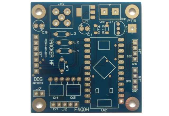 The PCB can produce a High Frequency RF signal in the range of 1MHz to 12.5MHz using an AD9833 Direct Digital Sequence (DDS) frequency synthesizer. The signal can be modulated with different Weak Signal modes such as WSPR, JT9 and JT65 using our Arduino 5V/16MHz Pro Micro software.
 -
 Integrating a _Software Defined Radio_ (SDR) into an existing ham radio setup involves connecting it with a standard transceiver (TRX), power amplifier (PA), and antennas. The core component is a splitter box that facilitates the connection between the TRX and the SDR, allowing for simultaneous operation without modifying existing equipment. In receive mode, the splitter ties the antenna inputs of both the TRX and a direct conversion receiver (DC RX) together. During transmission, the DC RX input is grounded via a fast telecom relay controlled by the transceiver's -SEND signal, incorporating a 10ms delay for safety. The splitter box includes a 3.7 dB input attenuator for impedance matching and acts as a protective fuse for the DC RX input. Ground loops are mitigated using common mode balun transformers, while the DC RX input is insulated with a broadband transformer. An audio switch box complements the setup, enabling users to listen to either the main transceiver, the SDR output, or both simultaneously. This configuration ensures noise immunity and safety, with the splitter housed in a screened box made from PCB material. On-air tests, such as the CQ WW 160m CW DX Contest, demonstrate the system's effectiveness, showcasing the SDR's ability to handle crowded band conditions with superior selectivity and dynamic range. The SDR's narrow bandwidth filters and waterfall display provide significant advantages, allowing operators to detect weak signals amidst strong interference. The integration of SDR with conventional radios offers enhanced operational flexibility and performance in challenging environments.