Search results
Query: homebrew dummy load
Links: 7 | Categories: 0
-
 This homebrewed antenna tuning unit also incorporates a 50-ohm QRP dummy load, power meter (1 or 10 Watts full scale), and SWR meter
 -
 Details a practical QRP wattmeter construction, leveraging a simplified SWR meter design by JA6HIC. The project focuses on a forward-only power measurement circuit, providing a functional instrument for RF power levels from milliwatts up to 5 watts. It maintains a 50-ohm input and output impedance, suitable for typical QRP transceivers and antenna systems. The resource includes the schematic for the "VSW" (Very Simple Wattmeter) and outlines a six-step alignment procedure. This calibration process involves using a known RF source up to 5W, setting full-scale deflection, and marking power increments. It also addresses minimizing frequency effects on readings with a 100pF trimmer capacitor, noting that measurement error is highest at the lower end of the scale. Construction notes mention using a piece of RG-213 coaxial cable for the inductance and coupler, with the wattmeter assembled in early 2003. The author provides an example measurement showing 0.8W into a dummy load and 1W into a 3-element beam.
 -
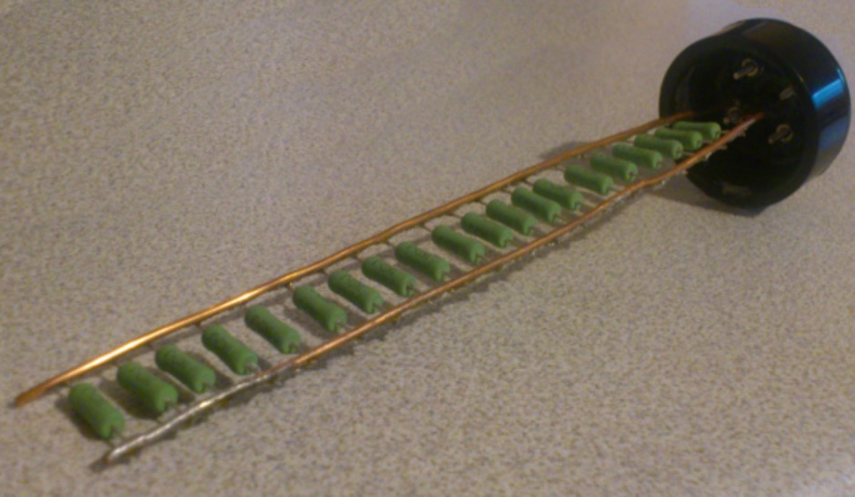
 A homebrew dummy load is usually a combination of several parallel carbon resistors, in order to be able a final resistance of 50 Ohms.
 -
 If your doing any home brewing gear for ham radio its a great idea to have a dummy load. This will to your radio be the perfect antenna...it will never radiate but your radio sees a perfect 50 Ohm impedance.
 -
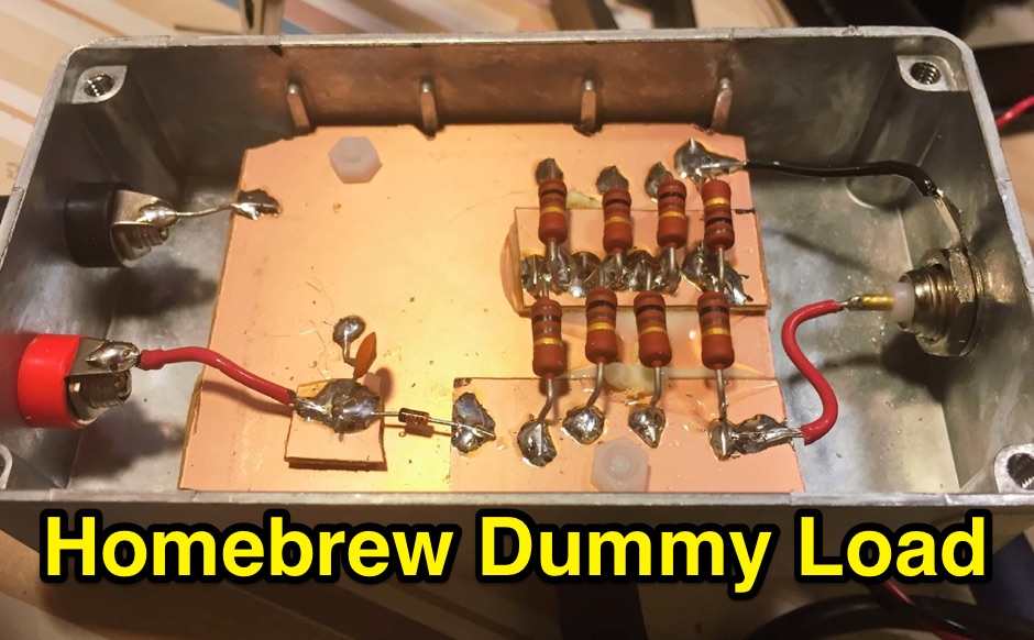 A simple 50 ohm dummy load to test transmitters. includes a simple RF diode detector to measure the peak voltage, and calculate the power
 -
-
 The project details the construction of a GM3OXX OXO transmitter, designed to accommodate **FT-243 crystals** using 3D-printed FX-243 holders from John KC9ON. It presents specific frequency adjustments, noting a 7030 KHz HC-49/s crystal could be tuned from 7029.8 KHz to 7031.7 KHz with an internal 45pF trimmer capacitor. The build incorporates a modified keying circuit to prevent oscillator run-on key-up and includes a TX/RX switch for sidetone via a connected receiver, with the transmitter output routed to a dummy load on receive. Practical construction aspects are thoroughly covered, including the process of cutting a rectangular opening in a diecast enclosure for the FT-243 socket and the selection of a **low-pass filter** (LPF) based on the QRP Labs kit, derived from the W3NQN design. The author achieved approximately 800mW output power from a 14.75V supply, measured with an NM0S QRPoMeter, using a 16.5-ohm emitter resistor in the 2N3866 final stage. The article also touches upon the potential for frequency agility across the 40M band using multiple FX-243 units with various crystals. The narrative includes a brief diversion into Bob W3BBO's recent homebrew projects, such as his Ugly Weekender MK II transceiver, highlighting the enduring appeal of classic QRP designs. The author reflects on the personal satisfaction derived from building RF-generating equipment, irrespective of DX achievements, and shares experiences of making local contacts with the 800mW OXO transmitter on 40 meters.