Search results
Query: 2 meter dipoles
Links: 28 | Categories: 2
Categories
-
 Portable, and shortened with loading coils rotatable dipoles for 6 meters, 20 meters and multibands.
 -
 Details the construction of a J-vertical antenna specifically for the 10-meter band, offering a practical alternative to a _Slim Jim_ design for 28 MHz. The resource outlines the use of aluminum tubing for the half-wave vertical section and coaxial cable for the quarter-wave matching section, providing specific calculations for element lengths based on frequency and coaxial cable velocity factor. It contrasts the performance of the J-vertical with center-fed dipoles and end-fed verticals, noting superior results in previous comparisons. The article further presents a more recent iteration of the J-vertical, constructed using a fiberglass pole and insulated wire, with updated dimensions for 28.8 MHz. It includes practical advice on weatherproofing connections and securing the antenna for durability against adverse conditions, referencing the survival of an original _J Vertical_ during 110 MPH winds in 1987. The SWR performance is reported as 1.1:1 at 28.6 MHz, maintaining below 1.5:1 across 28.3 to 29 MHz.
 -
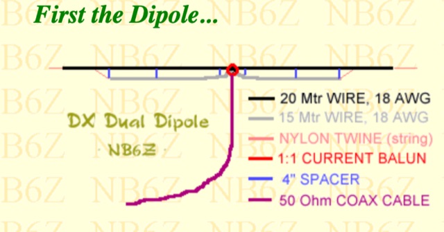 Two dipoles fed from the same coaxial line by n6bz for 20 and 15 meters
 -
 An efficient program to calculate dimensions of coax dipoles, or bazooka antennas considering velocity length of different coax cables. Express dimensions in feet/inch and meters/cm. Freeware by VE3SQB
 -
 The cobweb antenna it is basically a 5 band antenna comprising of 5 full half wave dipoles for each band - between 10 meters and 20 meters, the antenna is also resonant on 6M and can be modeled even for VHF frequencies.
 -
 Selecting an appropriate antenna system for shortwave broadcasting involves evaluating various types based on performance, cost, and operational parameters. This resource details the critical specifications for broadcast antennas, including average and peak power ratings, directivity, takeoff angle (TOA), horizontal beamwidth, and gain, emphasizing that a 100-kW transmitter requires an antenna rated for 150 kW average and 400 kW peak. It clarifies that low TOA signals travel thousands of kilometers, while high TOA is for local coverage, and nearly all modern shortwave broadcast antennas are horizontally polarized. The article explores specific antenna types, such as Log-Periodic Antennas (LPAs), which offer wide frequency ranges (e.g., 2-30 MHz) and directional patterns with 11 dBi gain, costing from $20K to over $100K for multi-curtain versions. Dipole arrays, also known as curtain antennas, are prevalent in international broadcasting, featuring steerable beams (±15° and ±30°) and mode-switching capabilities to alter TOA, with high/low pairs costing over $1 million. Fan dipoles are noted for omnidirectional patterns, smaller size, and lower cost for low-power applications, while rhombics, though simple, require resistive termination and incur several dB of I2R losses. Balun considerations are crucial, as most communications baluns are not rated for the higher average and peak powers of AM broadcast transmitters. Modern shortwave antennas utilize durable materials like Alumoweld wire rope for radiators and support elements, avoiding copper, fiberglass, or materials prone to stretching or deterioration. Feeder systems for high-power stations often require tapered-line baluns to convert 50-ohm unbalanced power to 300-ohm balanced for connection to the antenna.
 -
 Indoor multiband dipole with EZNEC data files for simulation and analysis. Includes details on construction, tuning, SWR plots, and software usage. This page includes two different dipoles, a first version for 20-10 meters and an extended version covering 40-10 meters allowing a full coverage of most used ham radio HF Bands.
 -
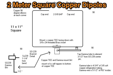 In this eHam article you will find parts list and dimension sheet for a 2m square dipole, made from copper plumbing fittings and 1/2 inch copper water pipe.
 -
 Rigid Dipole antennas for 14 MHz band using PVC and Aluminium tubing
 -
 Interesting article on mobile antennas by Cebik. . The article offers advice for setting up and operating mobile antennas for ham radio use. It emphasizes the lossy nature of mobile-in-motion antennas but encourages users to rise to the challenge. Steps include safeguarding car electronics, choosing proper cabling, and carefully selecting and mounting antennas. It highlights potential issues like roof mounting, trunk lip grounding, and side-mounting for trucks. For stationary operation, options like dipoles or beams are explored, with safety tips for masts and guying systems. Lastly, it stresses safety, suggesting stopping the vehicle to operate whenever possible
 -

-
 A 2-meter Turnstile antenna, detailed for amateur satellite communication, offers a straightforward build for those looking to engage with orbiting transponders. The author, WB8ERJ, shares his personal design and construction methods, emphasizing the antenna's simplicity and effectiveness for LEO (Low Earth Orbit) satellite work. This design provides a circularly polarized signal, crucial for mitigating _Faraday rotation_ and signal fading often encountered with linearly polarized antennas when tracking satellites. Construction involves readily available materials like PVC pipe and copper wire, making it an accessible project for many hams. The article includes practical advice on element spacing and feed point considerations, drawing from the author's hands-on experience in the shack and field. It highlights the antenna's utility for receiving signals from various amateur satellites, including the popular AO-91 and AO-92. The Turnstile's inherent omnidirectional pattern in the horizontal plane, combined with its circular polarization, yields consistent signal reception, often resulting in **stronger decodes** and **more reliable contacts** compared to basic dipoles or verticals.
 -
 End-Fed Half-Wave Antennas (EFHWAs) are analyzed for their utility in portable QRP operations, emphasizing their simplicity, efficiency, and predictable radiation patterns compared to other portable antenna types. The discussion contrasts EFHWAs with vertical antennas, random length wires, and center-fed dipoles, highlighting the common pitfalls of each, such as ground system dependency for verticals and feedline issues for dipoles. The article details the electrical half-wavelength calculation using the formula L (Ft) = 468/F(MHz) and explains how EFHWAs can be resonant on harmonic frequencies, enabling multiband operation. Various deployment configurations are presented, including the inverted L, inverted Vee, sloping wire, and vertical setups, each with specific advantages for radiation angle and polarization. For instance, a vertical EFHWA offers a low angle of radiation suitable for DX contacts without requiring an extensive ground system. The resource also addresses the counterpoise requirements, suggesting a quarter-wavelength wire or connection to a metallic structure for decoupling. A schematic diagram for a simple parallel-tuned circuit tuner, based on the _Rainbow Bridge/Tuner_ design, is provided, detailing component values for 30 and 40 meters, including a 6 microhenry toroidal inductor and a 20-100 picofarad mica compression capacitor. The tuner's adjustment process for SWR matching is also outlined.
 -
 This antenna consists of 4 resonate dipoles made from 12 insulated copper electrical wire. The dipoles are resonate on the following bands: 6 meters, 10 meters, 12 meters and 17 meters.
 -
 Over 1,000 stations in approximately 60 countries were worked using this modified twin-lead folded dipole, demonstrating its effectiveness with just 4 watts on 20 meters. This design, adapted from an ARRL Handbook concept, eliminates the shorting strap found in traditional folded dipoles, simplifying construction while maintaining performance. It utilizes readily available 300-ohm TV antenna feeder ribbon, making it a cost-effective solution for radio amateurs. The antenna's robust construction allows it to handle up to 100 watts without issues, even without a **balun**. The inclusion of a variable trimmer capacitor at the stub provides flexibility for tuning across different frequencies within a band, a practical feature for operators using transceivers like the Icom 735. Formulas are provided to calculate the precise dimensions for any desired operating frequency, enabling customization for various **HF bands**.
 -
 Experiments on HF antennas for restricted spaces. In this article author experiments antennas for 80-10 meters band having just a very small garden and several restrictions. Basic antennas consists of laded multiband dipoles and fan dipole antennas
 -
 This project details the construction of a **full-sized 40-meter vertical antenna**, born from a renewed interest in 7 MHz operation and a desire for improved effectiveness over simple dipoles. The author, K5DKZ, initially focused on VHF experimentation, which provided an inventory of aluminum tubing and fiberglass spreaders for this endeavor. Before this vertical, K5DKZ utilized an 80/40 meter inverted-vee trap dipole and a 40-meter broadband dipole, but now primarily uses a pair of full-sized, phased, quarter-wave verticals spaced 35 feet apart for serious 40-meter work. The construction involves a base-heavy design for stability, using a 44.5-inch section of 1-1/4 inch steel TV mast driven into 1-3/8 inch aluminum tubing, insulated by a 105-inch section of Schedule 40 PVC pipe. The assembly reaches 31 feet, close to the 32 feet required for a quarter-wavelength on 40 meters, with fine-tuning achieved by winding wire onto a fiberglass spreader. The design is explicitly presented as a foundation for a two-element 40-meter Yagi beam, outlining modifications like substituting aluminum for steel in the base and using an inductive hairpin match for the driven element. The article also discusses tuning considerations for a large 40-meter beam, noting the 100 to 200 kHz upward frequency shift when raised, and suggesting methods for installation on a tower. The author emphasizes the cost-effectiveness and good performance of the monopole approach, especially when multiple verticals are needed.
 -
 This antenna is intended for the 20-meter Band. There are two Voltage Fed Helical Dipoles, made with 2 slinky that fed with phase shift in 90 degree
 -
 Modeling compact 160 meter antennas, inverted L, half wave dipoles and linearly loaded dipole
 -
 22 Different Wire Antennas for the 160 Meter Band, Random Length Radiator Wire, delta loop, loop antennas, off-centered antennas, sloper, dipoles, Z antenna, Zepp and Clothesline Antennas
 -
 Slot cubes are folded skeleton slot antennas with widened, folded dipoles bent into a cube to reduce size. QST Article 12 2019
 -
 A presentation of the Yagi Antennas, and other interesting tid-bits by Brian Mileshosky. The document provides an in-depth exploration of the Yagi-Uda antenna, detailing its historical development, design principles, and performance characteristics. Originally described in the 1920s, the Yagi antenna features a driven element and parasitic elements, including reflectors and directors, which collectively determine its behavior. The document highlights how element lengths, diameters, and spacing influence gain, impedance, and directivity. It also discusses the antenna's reciprocal nature and presents data on typical gain values for various element configurations. Additionally, the text covers practical considerations, such as the construction of a "Tape Measure Yagi" for amateur use, and touches on related antenna types like dipoles and their application in Near Vertical Incident Skywave (NVIS) communication.
 -
 The 160-meter amateur radio band, spanning 1.8 to 2 MHz, was historically the lowest frequency amateur allocation until the introduction of the 630-meter and 2200-meter bands. ITU Region 1 allocates 1.81–2 MHz, while other regions use 1.8–2 MHz. This band, often called "Top Band" or "Gentleman's Band," was established by the International Radiotelegraph Conference in Washington, D.C., on October 4, 1927, with an initial allocation of 1.715–2 MHz. Effective operation on 160 meters presents significant challenges due to the large antenna sizes required; a quarter-wavelength monopole is over 130 feet, and horizontal dipoles need similar heights. Propagation is typically local during the day, but long-distance contacts are common at night, especially around sunrise and sunset, and during solar minimums. The band experienced a resurgence after the LORAN-A system was phased out in North America in December 1980, leading to the removal of power restrictions.
 -
 Complete collection of the four main parts of this excellet research on modelling and designing half wave dipole antennas for 40 meters band, covering all aspects beginning from full wave length antennas, to shortened, loaded and reshaped dipoles
 -
-
 Make them simple then Make them work. The LAZY H antenna is a general type of antenna that is in the curtain array family. By placing two 1 wavelength dipoles in a plane that is at right angles to the direction of maximum radiation and keeping the proper in-phase current condition to each element, you can achieve a high gain bi-directional antenna.
 -
 A 60-foot available space, for example, might necessitate a shortened multiband dipole array to cover 80, 40, and 15 meters effectively. This resource details the construction of such an antenna, combining full-size and coil-loaded dipoles on a single feedline. It addresses the common challenge of fitting multiple HF bands into restricted physical footprints, providing practical guidance for hams with smaller backyards or portable operations. The core of the offering is an interactive calculator that determines required loading coil inductance and dipole lengths for various amateur bands from 160m to 10m. Users input their available space, and the tool provides dimensions, coil turns, and an efficiency rating (Good or Fair) based on the antenna's electrical length relative to a quarter-wavelength. It also suggests suitable _PVC_ pipe diameters for coil forms. The article further illustrates a center feed-point assembly using an 18-inch section of 2-inch _PVC_ pipe, detailing eye-bolt spacing and coaxial connector installation. It emphasizes the importance of adequate spacing between parallel dipoles and offers customization options for the feed-point, including the addition of a _Balun_ for improved feedline isolation.
 -
 This article details a ham radio operator’s experience setting up HF antennas in an antenna-restricted community. Initially using an AEA Isoloop magnetic loop for QRP PSK, the author later built an attic antenna system, including dipoles for multiple HF bands and a slinky dipole for 40 meters. The setup allowed for operation on six bands with acceptable VSWR. Despite space constraints and some compromises, performance was effective. The article highlights practical strategies, emphasizing experimentation and antenna modeling for optimizing performance in limited-space environments. A valuable guide for ham radio operators facing similar restrictions.