Search results
Query: 20 mhz antenna
Links: 184 | Categories: 2
Categories
-
 Demonstrates the construction of a **multi-band HF mobile antenna** utilizing a modified CB whip antenna base. The resource details the process of stripping a commercial CB whip, winding a new helical coil with 0.7mm insulated copper wire, and identifying tapping points for various HF bands. It emphasizes the importance of a rugged, slim design for mobile operation, discussing mechanical length, power handling (up to 200 watts), and coil diameter considerations. The article includes a graphic illustrating the antenna's operational principle, where sections of the helical coil are shorted from bottom to top to maintain efficiency and high Q. The resource presents a practical approach to achieving **band switching** without an external tuner, by manually adjusting tapping points on the coil. It provides a table with reference lengths in centimeters from the feedpoint for 7 MHz (40m) through 28.7 MHz (10m), including WARC bands. The author details mounting techniques, suggesting a Diamond bracket for secure attachment to a vehicle trunk, and stresses the critical role of proper grounding for optimal performance. The design allows for operation on 75m and 80m bands by adding a 110mm steel whip.
 -
 A 10-20 meters coverage delta loop antenna. After relocating, DL2HCB designed a multiband loop antenna to cover 10-20m with an open-wire feed for impedance matching and compact installation. Inspired by the mini-X-Q design, a modified 10m delta-loop was built, enhanced with a 1/4 wave shorted stub for 28 MHz using 450-ohm ladder line. The antenna delivers east-west broadside radiation and performs as a closed loop on other bands. Operational tests yielded strong European signals and successful DX contacts, including a 20m QRP QSO with FY/DJ0PJ.
 -
 The G5RV antenna, with an overall length of **31.10m (102ft)**, functions as a 3/2-wave on 20 meters when installed horizontally at 12m (39ft), exhibiting a resonant frequency of 14.150MHz and an approximate resistance of 80 ohms. Its 10.36m (34ft) stub line, designed as a 1/2-wave on 14.150MHz with a 0.97 velocity coefficient, acts as an impedance transformer across other bands, aiming for multiband operation without traps. On 20m and higher frequencies, the G5RV demonstrates improved gain compared to a standard dipole, attributed to the _collinear effect_ from multiple 1/2-waves along the wire. The original design sought a multiband solution for limited spaces, often requiring an Antenna Tuning Unit (ATU) for effective operation across bands like 80, 40, 30, and 20m, particularly with modern solid-state PAs. Variants, such as the F8CI modification, incorporate a 1/4 current balun at the stub line's base for symmetrical-to-asymmetrical transition, known as a _remote balun_. Proper flat-top or inverted-V installation is critical for maintaining symmetry and collinear gain, with inverted-V apex angles below 120° progressively diminishing higher-band performance.
 -
 Demonstrates the construction of **magnetic loop antennas**, detailing both multi-turn and single-turn designs. It covers a 30-inch diameter multi-turn loop for 80 meters, based on a February 1996 QST article, and an octagon single-turn loop made from 15mm copper tube with a 4.8-meter circumference, operating from 7 MHz to 14 MHz. The document also presents a smaller 800mm diameter loop for 14 MHz to 28 MHz, emphasizing the importance of high-voltage tuning capacitors. Covers the design and construction of custom **butterfly capacitors** and piston capacitors, including a split stator capacitor with 140 pF capacitance and a 6000 Volt rating, and a butterfly capacitor with 5-65 pF and 7200 Volt rating. It explains why butterfly capacitors are preferred over split stator types for high power applications due to lower losses and direct series connection of rotors, reducing resistive losses from wiper contacts. Material recommendations include clear PVC for plates and brass or stainless steel for non-magnetic hardware. Addresses practical considerations such as feeding the loop with a shielded 1/5 Faraday loop made from RG213 or RG8 coax, achieving VSWR 1.1 across bands, and optimizing its placement 180° from the capacitor. It also discusses mechanical joint resistance, dissimilar metal oxidation prevention using Vaseline, and a simple method for determining radiation angle with a TL-light tube. The guide includes diagrams for rotor, stator, and end plate construction.
 -
 The **Extended Double Zepp** (EDZ) antenna, a simple wire design, is presented as a means to achieve 3-4 dB of gain on 10 meters, with an overall length of just 43 feet. This resource, authored by WB3HUZ, details several gain antennas suitable for the 29 MHz AM segment, all modeled using EZNEC software at 30 feet above ground. Other designs include a compact rectangular loop, offering more gain than the EDZ and a lower take-off angle, and the **Lazy H**, a bidirectional antenna providing 6 dB gain, which is also workable on 20, 17, 15, and 12 meters. The Bisquare, a diamond-shaped open-top loop, is also featured, providing approximately 4 dB gain and requiring only a single support. These designs are primarily fed with ladder line or open-wire line to simplify matching, though a coax feed option for the EDZ is shown for 10-meter-only operation. The Lazy H, for instance, requires about 16 feet of open-wire line for its half-wavelength elements spaced a half-wavelength apart. An enhanced EDZ Lazy H variant is also discussed, achieving an additional 1-2 dB gain by extending element length to 1.28 wavelengths and increasing spacing to 0.64-0.75 wavelengths. The Bisquare, while primarily a 10-meter antenna, can be adapted for 20 meters by closing the top connection.
 -
 This PDF article from April 2001 QST details the construction of the "NJQRP Squirt," a reduced-size 80-meter inverted-V dipole antenna. The resource provides a general construction sketch, a photograph of the assembled antenna, and specific dimensions for PC-board insulators. The antenna consists of two wire legs, each approximately **34 feet long**, separated by 90 degrees, fed at the center. It is designed for operation on 80 meters (3.5-4.0 MHz) as a quarter-wavelength antenna, requiring a low-loss feedline and an external antenna tuner due to its non-resonant feedpoint impedance. Construction utilizes readily available materials, including 1/16-inch glass-epoxy PC board for end and center insulators, and #20 or #22 insulated hookup wire for the elements. The feedline specified is 300-ohm TV flat ribbon line, with a note on potential trimming for tuner compatibility. N2CX reports the antenna's center should be elevated to at least **20 feet**, with ends no lower than seven feet above ground, resulting in a ground footprint of approximately 50 feet wide. The design prioritizes NVIS propagation for local 80-meter contacts. DXZone Focus: PDF Article | 80m Inverted-V Dipole | Construction Notes | 34 ft element length
 -
 The RXO Unitenna, a vertical wideband antenna, offers operation across the 7-21 MHz spectrum, covering the 40, 30, 20, 17, and 15-meter amateur bands. This design focuses on achieving a low SWR across a broad frequency range, making it suitable for general HF operation without requiring an external antenna tuner for minor SWR variations. The antenna utilizes a unique loading coil and matching network to maintain efficient radiation characteristics across its operational bandwidth. Construction details within the PDF document include specific dimensions for the radiating element and the counterpoise system, which is critical for vertical antenna performance. The design incorporates readily available materials, simplifying the build process for radio amateurs. Performance graphs illustrate the SWR characteristics across the 7 MHz to 21 MHz range, demonstrating the antenna's wideband capabilities. The document also provides guidance on feedline connection and grounding considerations for optimal field deployment. This vertical antenna configuration is particularly useful for hams with limited space, offering a compact footprint compared to horizontal wire antennas.
 -
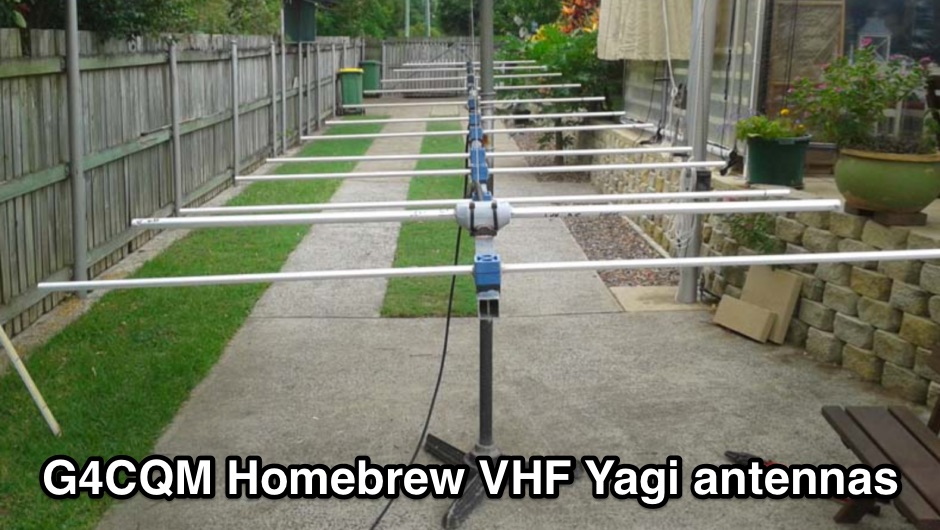 Homebrew VHF Yagi 50MHz 144MHz 432MHz 1296MHz 2320MHz 6M 2M 70CM 23CM 13CM Yagis
 -
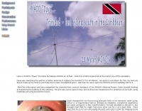
 Pictures and plans of a 4 elements yagi beam antenna for 14 Mhz
 -
-
 The multi-band trapped dipole is resonant on approx 3.7, 7, 14, 24 7 28.5 Mhz. The overall top length needs to be approximately 32.9 Meters
 -
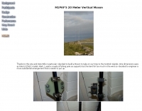 A 14 Mhz version of the vertical moxon antenna homebrewed.
 -
 Demonstrates the construction and performance of an updated ZS6BKW multiband dipole, a variant of the _G5RV_ antenna, specifically designed for HF operation. The article details a real-world installation using 13.5m copper wire elements and 12.2m of 450 Ohm ladder line, configured as a sloping inverted-V with the apex at 10m and ends at 4m above ground. It covers the critical aspect of impedance matching, incorporating an 8-turn choke balun at the feedline transition to RG-58U coax to mitigate RF common mode current. Measurements confirm favorable SWR readings below **1.3:1** on 7.1 MHz, 14.11 MHz, 18.06 MHz, and 24.8 MHz, indicating effective resonance across 40m, 20m, 17m, and 12m bands. The installation also shows usable SWR dips on 3.55 MHz (5:1), 29.02 MHz (2:1), and 50.84 MHz (3:1), extending its utility to 80m, 10m, and 6m with an antenna tuning unit. Initial on-air results report clear reception of stations over **5000km** away, validating its DX potential.
 -
 A delta loop wire antenna plan for the 7 MHz band (40 meters) that is quick to setup and work with
 -
 Selecting an appropriate antenna system for shortwave broadcasting involves evaluating various types based on performance, cost, and operational parameters. This resource details the critical specifications for broadcast antennas, including average and peak power ratings, directivity, takeoff angle (TOA), horizontal beamwidth, and gain, emphasizing that a 100-kW transmitter requires an antenna rated for 150 kW average and 400 kW peak. It clarifies that low TOA signals travel thousands of kilometers, while high TOA is for local coverage, and nearly all modern shortwave broadcast antennas are horizontally polarized. The article explores specific antenna types, such as Log-Periodic Antennas (LPAs), which offer wide frequency ranges (e.g., 2-30 MHz) and directional patterns with 11 dBi gain, costing from $20K to over $100K for multi-curtain versions. Dipole arrays, also known as curtain antennas, are prevalent in international broadcasting, featuring steerable beams (±15° and ±30°) and mode-switching capabilities to alter TOA, with high/low pairs costing over $1 million. Fan dipoles are noted for omnidirectional patterns, smaller size, and lower cost for low-power applications, while rhombics, though simple, require resistive termination and incur several dB of I2R losses. Balun considerations are crucial, as most communications baluns are not rated for the higher average and peak powers of AM broadcast transmitters. Modern shortwave antennas utilize durable materials like Alumoweld wire rope for radiators and support elements, avoiding copper, fiberglass, or materials prone to stretching or deterioration. Feeder systems for high-power stations often require tapered-line baluns to convert 50-ohm unbalanced power to 300-ohm balanced for connection to the antenna.
 -
 Rigid Dipole antennas for 14 MHz band using PVC and Aluminium tubing
 -
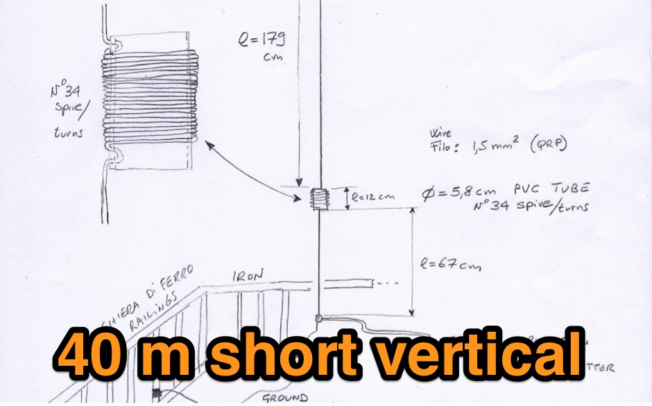
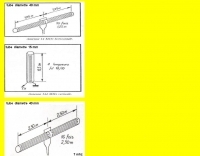 Drawings of shortened antenna for indoor usage, using short pvc tubes for 2 , 20 and 40 MHz by f1rfm
 -
 This page describes the loading coil (inductor) that W8WWV built for my center-loaded 160 meter band (1.83 MHz) vertical antenna.
 -
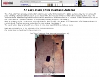
 A 10-meter J-Pole antenna, detailed in QST February 1950, offers a straightforward solution for hams operating with restricted space. This design, originally presented by W1BLR, is a **half-wave radiator** fed by a quarter-wave matching stub, providing a low-angle radiation pattern beneficial for DX. The article describes building the antenna from readily available materials like copper pipe, emphasizing its simplicity and effectiveness for **single-band operation**. The J-Pole's inherent design provides a good impedance match to 50-ohm coaxial cable without the need for an external tuner, a significant advantage for portable or minimalist stations. Its nondirectional pattern ensures coverage in all directions, making it a versatile choice for general operating on the 28 MHz band. The construction plans are clear, allowing even those with basic workshop skills to assemble a functional antenna.
 -
 Inverted vee dipole antenna for 20 meters band by VK1OD
 -
 A shortened and invisible wire antenna for 7 MHz
 -
 The ZS6BKW multiband HF antenna, a design by ZS6BKW (G0GSF), functions effectively on multiple HF bands without requiring an Antenna Tuning Unit (ATU) for 40, 20, 17, 12, 10, and 6 meters. This antenna, approximately **27.51 meters** (90 feet) long with a 12.2-meter (40-foot) open-wire feeder, is a direct descendant of the _G5RV_ but offers superior multi-band resonance. It can be deployed as a horizontal dipole or an inverted-vee, with the latter requiring only a single support and maintaining an apex angle of at least 90 degrees to prevent signal cancellation. Performance data, recorded with an MFJ Antenna Analyser, indicates SWR values of 1:1 on 7.00 MHz (40m) and 14.06 MHz (20m), with SWR below 1.3:1 on 17m, 10m, and 6m. While primarily designed for these bands, the antenna can be adapted for 80m, 30m, and 15m with an ATU, preferably at the balanced feeder's base. The use of 450-ohm twin-lead for the feeder is recommended over 300-ohm for improved strength and reduced losses, especially in adverse weather conditions. This design, originally published in _RadCom_ in 1993 and featured in Pat Hawker’s "Antenna Topics," provides a compact and efficient solution for HF operation, particularly for those with limited space or resources.
 -
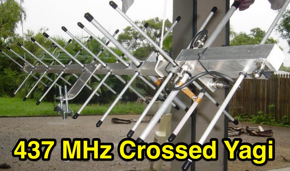 Crossed yagi for 437 MHz Satellite antenna, with power divider splitter build.
 -
 A rotary trapped-dipole for 17 and 20 meters, as described by IZ7ATH, presents a practical solution for multi-band HF operation. The author, Talino, recounts his experience building this antenna for IK7ZCQ, detailing the evolution from an initial concept involving a grounded-driven element and gamma-match to a direct-fed, non-grounded design. His pragmatic approach, adapting available materials, is evident throughout the construction narrative, particularly with the use of eight tapered aluminum pipes for the driven element. Construction specifics include precise measurements for the aluminum tubing, with diameters ranging from 30 mm down to 16 mm, and a critical note on reducing tip thickness for weight optimization. The _traps_, initially a concern, are fabricated using 8 turns of RG58 coax on a 27 mm support, tuned to resonate at 18.1 MHz using a dip-meter. Talino emphasizes sealing the traps with RF glue and PVC tape to prevent water ingress, a crucial step for longevity. Field test results, conducted on a 10-meter pole in a clear garden environment, showed an SWR of 1.2:1 on 17 meters and 1.5:1 at 14.200 MHz. While SWR varied slightly when installed at Mario's QTH due to nearby objects, the antenna's performance remained commendable. The final half-dipole length is 46 cm for the 18 MHz tips, and the total weight is under 6 kg, with potential for further reduction.
 -
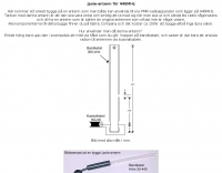
 20 meter wire j-pole for 14.2 MHz, a vertical, end-fed half wave antenna by N1LO
 -
 A homebrew project for a 2 meter 4 element yagi beam antenna by 2E0HTS
 -
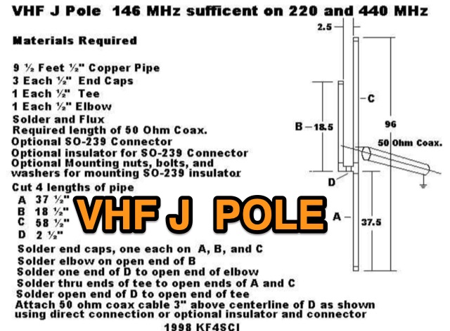 KF4SCI picture of a project for a VHF UHF jpole antenna working on 220 and 440 MHz.
 -
 Rugged, disguised 2m, 220MHz, 440MHz, and 2m/440 dual band antennas, HF portable antennas, portable dipoles.
 -
-
-
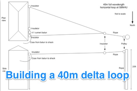 Building a 40m (7MHz) horizontal delta loop wire antenna in the backyard that is easy and quick to setup
 -
 End-Fed Half-Wave Antennas (EFHWAs) are analyzed for their utility in portable QRP operations, emphasizing their simplicity, efficiency, and predictable radiation patterns compared to other portable antenna types. The discussion contrasts EFHWAs with vertical antennas, random length wires, and center-fed dipoles, highlighting the common pitfalls of each, such as ground system dependency for verticals and feedline issues for dipoles. The article details the electrical half-wavelength calculation using the formula L (Ft) = 468/F(MHz) and explains how EFHWAs can be resonant on harmonic frequencies, enabling multiband operation. Various deployment configurations are presented, including the inverted L, inverted Vee, sloping wire, and vertical setups, each with specific advantages for radiation angle and polarization. For instance, a vertical EFHWA offers a low angle of radiation suitable for DX contacts without requiring an extensive ground system. The resource also addresses the counterpoise requirements, suggesting a quarter-wavelength wire or connection to a metallic structure for decoupling. A schematic diagram for a simple parallel-tuned circuit tuner, based on the _Rainbow Bridge/Tuner_ design, is provided, detailing component values for 30 and 40 meters, including a 6 microhenry toroidal inductor and a 20-100 picofarad mica compression capacitor. The tuner's adjustment process for SWR matching is also outlined.
 -
 This PDF document, authored by KT4QW in October 2004, details the construction and modeling of a dual-band, horizontally polarized hanging rectangular loop antenna for **10 and 17 meters**. The design, adapted from *The ARRL Handbook*, utilizes _NEC4WIN95_ software for scaling and optimization, targeting a 50 ohm feedpoint impedance. The resource includes a bill of materials, step-by-step construction instructions, and a discussion of the antenna's radiation characteristics. It presents NEC-generated elevation and azimuth patterns, comparing the loop's performance to a half-wave horizontal dipole at the same height and frequency. The 17-meter element is centered at 18.140 MHz for low SWR across the phone band, while the 10-meter element is centered at 28.500 MHz. Construction involves 14-gauge stranded copper wire and Schedule 40 PVC spreaders, with the total wire length calculated by the formula: Length in feet = 1005/MHz. The feedpoint impedance can be adjusted by modifying the rectangular aspect ratio. The document specifies hoisting the antenna to at least a half-wave above ground for testing. It notes that a balun was tested and found to have no measurable effect on SWR or radiation characteristics. A 2-meter scale model is presented to illustrate the physical design, and a "rotator" string is incorporated for directional adjustment up to 90 degrees.
 -
 A multiband end-fed antenna that cover 3.5 to 30 Mhz using a 1:64 Balun based on a FT240-43 core
 -
 An homebrew project for a 3 elements yagi monoband antenna for the 20 meters by 9M2MSO
 -
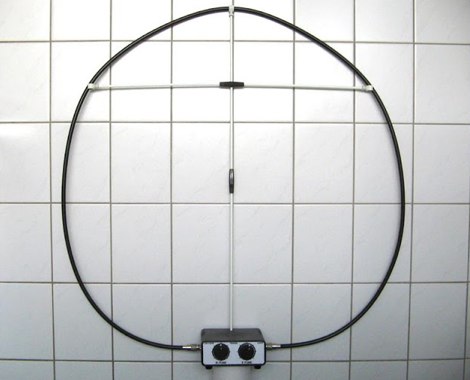 PA11019 Travel loop antennas, these antennas cover 6.300 to 29.200 mHz , handle 35 Watts and have a packing size of 43 cm, ideal for fieldwork, or mobile operations.
 -
 Manufacturer of Fibreglass Whip Antennas, Low and mediun Frequency, HF and VHF Antennas Specialized in the design and manufacturing of a full range of Beacon (MF), AM Broadcasting 540 - 1700 KHz, HF 1.7 to 30 MHz, VHF 30 to 156 MHz and UHF 200 to 500 MHz antennas.
 -

-
 The article "Exploring the World of 10 Meter Beacons" by Ken Reitz, KS4ZR, provides an in-depth look at 10-meter beacon operations, focusing on their utility for propagation analysis. It details FCC Rules part 97.203 governing beacon stations, including license requirements, power limits (under 100 watts), and the specified band segment of 28.200-28.300 MHz for U.S. operations. The content highlights the diversity in beacon construction, from converted CB radios to home-brew QRP transmitters, and discusses the robust operating conditions these 24/7 stations endure. The resource presents several case studies of active 10-meter beacon operators like Ron Anderson KA0PSE/B, Domenic Bianco KC9GNK/B, and Bill Hays WJ5O/B, detailing their equipment, antenna setups, and typical signal report volumes. It also introduces the NCDXF/IARU International Beacon Project, which features 18 synchronized beacons worldwide transmitting on 28.200 MHz at varying power levels (100W, 10W, 1W, 100mW) to facilitate propagation testing. The article also covers the PropNet Project utilizing PSK31 on 28.131 MHz and the 250 Synchronized Propagation Beacon Project on 28.250 MHz. Practical advice for monitoring includes using the RST reporting method, understanding the impact of the solar cycle on 10-meter propagation, and tips for setting up a personal beacon, such as frequency selection and power output considerations. The IY4M Guglielmo Marconi Memorial Beacon Robot on 28.195 MHz is also mentioned for its automatic QSO mode. The article concludes with a list of other resources for 10-meter beacon information.
 -
 The G5RV antenna, a popular multi-band wire antenna, typically employs a center-fed design with a specific length of 300-ohm or 450-ohm open-wire line acting as an impedance transformer, feeding a coaxial cable run to the shack. Its overall length for 80-10 meters is approximately 102 feet (31 meters) for the flat-top section, with a 34-foot (10.36 meter) matching section. The original design by Louis Varney, G5RV, aimed for efficient operation on 14 MHz (20 meters) as a 3-half-wave antenna, with the matching section providing a good match to 50-ohm coax on that band. While the G5RV offers multi-band capability, its performance varies across bands, often requiring an antenna tuner for optimal SWR on bands other than 20 meters. The matching section's length is critical for its impedance transformation properties, influencing the feedpoint impedance presented to the coaxial cable. Variations like the G5RV Junior and ZS6BKW utilize different flat-top and matching section lengths to optimize performance for specific band sets or to achieve a lower SWR without a tuner on certain bands, demonstrating the adaptability of the basic G5RV concept.
 -
 An experimental fractal Quad antenna for 10 meter band project by AG1LE
 -
 A 7 elements yagi beam monoband antenna for 14 Mhz by VE3GK
 -
 A base station antenna you can easily build for 146,220 or 440 MHz, with performance similar to a J-pole but smaller and less obstrusive
 -
 An homebrewed dipole antenna for 14MHz
 -
 This halo antenna was built to have an omnidirectional coverage while working in VHF contests.
 -
 JJ0DRC's HF multi-band delta loop antenna project, initially conceived during the waning peak of Cycle 23, addresses the common challenge of achieving effective DX operation from a small residential lot in Japan. Dissatisfied with a ground plane antenna's performance in SSB pile-ups, the author sought a beam-like solution without a tower, drawing inspiration from a JJ1VKL article in CQ Ham Radio Sep. 2000. The antenna, constructed in October 2000, employs two 7.2-meter fishing rods (37% carbon fiber, reinforced with cyano-acrylate glue and aluminum tape) and 1mm enameled wire, fed by an Icom AH-4 external antenna tuner. While the exact beam pattern remains unmeasured, JJ0DRC observed a significantly higher callback rate compared to dipole antennas, particularly on higher bands. The system's circumference length of 15-20m is crucial for maintaining a good beam pattern across HF bands, though performance on lower bands like 80m, 40m, and 30m becomes less directional as the length deviates from a full wavelength. Ongoing maintenance addressed degradation issues, including aluminum tape cracking and wire breakage at connection points due to strong winds (often exceeding 10-15m/s in winter). The author reinforced rod connections with IRECTOR PIPE SYSTEM components and INSU-ROCK ties, and improved wire attachment methods using Cremona rope and epoxy bond to enhance durability.
 -
 This resource details the computer-optimized design of the _ZS6BKW_ multiband dipole, an evolution of the classic _G5RV_ antenna. It begins by referencing the original 1958 RSGB Bulletin article by Louis Varney G5RV, explaining the operational principles of the G5RV's flat-top and open-wire feedline on 20m and 40m, noting its impedance transformation characteristics for valve amplifiers of that era. The article then transitions to the rationale for optimizing the design for contemporary solid-state transceivers requiring a 50 Ohm match. The core of the project involves using computer modeling to determine optimal lengths for the flat-top and matching section, aiming for a VSWR of less than 2:1 on multiple HF bands. It discusses the process of calculating feedpoint impedance based on antenna length and frequency, referencing professional literature from Professor R.W.P. King at Harvard University. The analysis also considers the characteristic impedance (Z(O)) of the open-wire line, identifying a broad peak of adequate values between 275 and 400 Ohms. Specific design parameters for the improved ZS6BKW are presented, including a shorter flat-top and a longer matching section compared to the original G5RV, with a velocity factor of 0.85 for the 300 Ohm tape. The article confirms acceptable matches on 7, 14, 18, 24, and 28 MHz bands when erected horizontally at 13m, and also discusses performance in an inverted-V configuration, noting frequency shifts. The author, Brian Austin ZS6BKW, emphasizes the antenna's suitability for modern 50 Ohm coaxial cable without a balun.
 -
 Demonstrates the construction of two distinct wideband RF preamplifiers, detailing their component requirements and performance characteristics. The first design leverages monolithic microwave integrated circuits (MMICs) such as the MAR-6, MAR-8, or PGA103, offering a broad frequency response from DC to 2 GHz with a gain of 22.5 dB at 100 MHz and a noise figure typically below 3 dB. This MMIC-based amplifier incorporates protection against power supply transients and features a 50 Ohm input/output impedance, operating from an 8-20 volt supply with low current drain. The second preamplifier design utilizes a BSX-20 transistor, providing amplification across the 14 MHz to 550 MHz range. This simpler, more economical build achieves an average gain of 12 dB at 145 MHz and a noise figure of approximately 1.1 dB. It operates from a 7-15 volt battery supply with a current draw of 6 mA. Both projects emphasize critical construction techniques, such as maintaining short RF connections, ensuring 50 Ohm impedance paths, and mounting the circuit within a shielded enclosure to optimize performance and minimize noise. The resource also discusses phantom power options for antenna-mounted preamplifiers and precautions for use with transceivers, including output protection diodes and static bleeders.
 -

-
