Search results
Query: 40 80 160 meter antenna
Links: 23 | Categories: 0
-
 Build a space efficient trapped dipole antenna for 40-80-160 meter bands using RG-58 and PVC pipe. The document provides a brief guide on building a compact dipole antenna appropriate for the 40, 80, and 160-meter amateur radio bands. It explains the materials, building processes, and tuning methods required to provide best performance while preserving space. The paper also discusses theoretical elements of dipole antennas, such as impedance matching and feedline selection.
 -
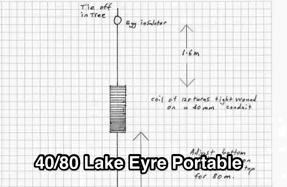 Portable wire antenna for 40 and 80 meter made with a RF Chocke. Can be adapted to work on 160 meters by adding additional 6.9 meters wire at its end.
 -
 A multiband 80-40-20-15 meters dipole wire antenna that can be extended to cover 160 meters too.
 -
 This is a custom home made antenna, based on concept of commercial HF antennas, that may work on 160 meters too.
 -
 The Bruce array is a simple, often-forgotten wire antenna array that is advantageous for 80 and 160 meters, where typical gain antennas are very large. This bi-directional broadside vertical array is only 1\4 lambda high and does not require a ground system. It offers substantially greater SWR bandwidth than the half-square or bobtail curtain. A 4-element Bruce array used by N6LF showed a gain of about 4.6 dB compared to a 1\4 lambda vertical with 8 elevated radials, with a 2:1 SWR bandwidth greater than 400 kHz. The antenna is simple and its dimensions are flexible.
 -
 This PDF File desscribes how to homemade a multi-band end-fed trapped wire antenna resonating on the low bands of 160 80 and 40 meters. Contains trap design instructions and some construction tips.
 -
 This document by W4HM explains the construction and usage of a 160 meter balanced coaxial receiving loop antenna, which can be easily adapted for the 40 and 80 meters bands. The content provides detailed instructions on building the antenna, its advantages, and how to optimize its performance for amateur radio operations. It is a valuable resource for radio amateurs looking to improve their receiving capabilities and enhance their overall radio communication experience.
 -
 The basic antenna is a vertical monopole, using elevated radials to complete the ground plane by k5oe
 -
 Article on the HF dual band antenna with construction details and how to add 160 meters to the HF2V
 -
 3 Band vertical Marconi-antenna for the bands 40, 80, 160 meters with a ground net of wires as radials.
 -
 A 90-foot vertical antenna constructed from **aluminum irrigation tubing** is detailed, focusing on its innovative raising and lowering mechanism. The resource describes a **45-foot ginpole** system, allowing a single operator to erect or lower the antenna in minutes. It covers the mechanical design, including the pivot base, insulated joints for the tubing sections, and guy wire attachment points. The antenna consists of two 30-foot sections of 4-inch tubing and one 30-foot section of 2-inch tubing, stacked with the smaller diameter at the top. The electrical design incorporates PVC "condulet" boxes at the 30-foot and 60-foot points, housing relays to change the effective height for multi-band operation on 160, 80, 40, and 30 meters. Ferrite rod inductive chokes are used for DC control and to tune out gap capacitance. The antenna is fed with 1000 feet of open wire line, connected to a matching transformer comprising stacked toroids and a coaxial/toroidal balun. Grounding is achieved with a 3x3 foot grid of 16-gauge tinned copper wires with soldered crossovers.
 -
 One specific challenge in the KazShack, operating Single Operator Two Radios (SO2R), involved sharing a K9AY receive antenna between two transceivers without direct RF connection or manual feedline swapping. The solution, detailed in this project, adapts the **W3LPL RX bandpass filter** design to split 160m and 80m signals, feeding them to separate radio inputs while maintaining isolation. This approach also addresses the issue of strong broadcast band interference from a nearby 50KW WPTF transmitter on 680kc. The construction utilizes T-50-3 toroids and NP0 ceramic capacitors, built in a "dead bug" style on copper clad board. Each band's filter coils are identical and resonated to the desired frequency using an MFJ-259 antenna analyzer. A single DPDT relay, controlled by a remote toggle switch mounted on an aluminum panel, facilitates quick band switching between radios, simplifying low-band operations. While some signal loss is noted, the expected lower noise levels from the receive antenna are anticipated to compensate, potentially reducing the need for constant volume adjustments during toggling between transmit and receive antennas.
 -
 The X80 multi-band HF vertical antenna, a commercial iteration of the Rybakov design, exhibits a physical length of 5.5 meters, or approximately 18 feet, and is constructed from aluminum tubing. It operates as a non-resonant vertical, requiring an external antenna tuner for impedance matching across its intended operating frequencies. The antenna's design incorporates a 1:4 UNUN at its base, facilitating a nominal 50-ohm feed point impedance for the coaxial cable. Performance observations indicate effective operation on 40 meters, 20 meters, 15 meters, and 10 meters, with reduced efficiency on 80 meters and 160 meters due to its relatively short electrical length for these lower bands. Comparative analysis with a G5RV dipole and a half-wave end-fed antenna reveals the X80 offers a lower take-off angle, beneficial for DX contacts, particularly on the higher HF bands. Field tests conducted with an Icom IC-706MKIIG transceiver and an LDG AT-100ProII autotuner demonstrate the X80's ability to achieve acceptable SWR across 80m through 10m. The antenna's compact footprint and ease of deployment make it suitable for restricted spaces or portable operations, though its performance on 80 meters is noted as a compromise compared to full-size resonant antennas.
 -
 A presentation of a HF multi-band sloper antenna. This antenna project is for low band operations, and antenna presented in this article works on 40 80 and 160 meters band. Article is in Polish.
 -
 The ZS1J/B beacon operates on 28.2025 MHz with 5 Watts output to a half-wave, end-fed vertical antenna, initially installed in 1977 as ZS5VHF near Durban. The 10-meter transmitter is a modified 23-channel CB radio, and the identification keyer uses a diode matrix unit with TTL ICs from the same era. After relocation to Plettenberg Bay in 1993, the beacon has been in continuous service, with additional QRP transmitters later installed for other bands. In 1994, a single-transistor, 80-meter, 0.5-watt QRP transmitter with a half-wave dipole was added on 3586 kHz, followed by a 160-meter, 0.5-watt unit on 1817 kHz. A 30-meter, 0.5-watt transmitter was installed in 1996, operating on 10.124 MHz. In 2002, a 40-meter QRRP beacon on 7029 kHz, with an output of 100 microwatts, achieved DX reports up to 1100 km from ZS6UT in Pretoria. Best DX reports for the 80m and 160m beacons came from 9J2BO.
 -
 This type of antenna is a popular antenna design as the performance is very good across the HF bands and requires little or no tuning. It’s a dipole fed off center with a 4:1 balun at the offset feed point. The antenna shown covers 80, 40, 20 and 10 meters. The formula can also be used to adjust the overall length to cover more or fewer bands and the resulting overall length. 160-10m, 80-10m or 40-10 meters depending on your available space. Other bands will require a tuner.
 -
 A 3 band dipole antenna for 40-80-160 meter bands, It's made with easily available materials and is designed for inverted V mounting. The antenna is shortened for these bands, but still manages to make contacts in 80m and 160m with stations in Canada and the USA. The construction details are provided, including the dimensions of the antenna elements and the traps. The antenna is easy to build and provides good performance in all three bands. In Italian.
 -
 A 60-foot available space, for example, might necessitate a shortened multiband dipole array to cover 80, 40, and 15 meters effectively. This resource details the construction of such an antenna, combining full-size and coil-loaded dipoles on a single feedline. It addresses the common challenge of fitting multiple HF bands into restricted physical footprints, providing practical guidance for hams with smaller backyards or portable operations. The core of the offering is an interactive calculator that determines required loading coil inductance and dipole lengths for various amateur bands from 160m to 10m. Users input their available space, and the tool provides dimensions, coil turns, and an efficiency rating (Good or Fair) based on the antenna's electrical length relative to a quarter-wavelength. It also suggests suitable _PVC_ pipe diameters for coil forms. The article further illustrates a center feed-point assembly using an 18-inch section of 2-inch _PVC_ pipe, detailing eye-bolt spacing and coaxial connector installation. It emphasizes the importance of adequate spacing between parallel dipoles and offers customization options for the feed-point, including the addition of a _Balun_ for improved feedline isolation.
 -
 Experimentin wire antennas on top band using several type of aerials. This includes a 40 to 160 meters EndFed Half Wave kite antennas and 160m/80m loaded vertical antenna.
 -
 This antenna is designed for 40, 80 and 160 meters to complement a tri-band beam normally taken on DX peditions for 10, 15 and 20 meters, so six bands can be worked with only two antennas.
 -
 Discover the best low band receive antennas for hams with limited space. Learn about the K9AY loop antenna and Shared Apex Loop Array, two alternatives to the traditional Beverage antenna. Understand the concept of Relative Directivity Factor (RDF) and compare the performance of different receive antennas. See how the Shared Apex Loop, patented by Mark Bauman (KB7GF), offers an RDF between 8 and 10dB. Find out how to optimize antenna performance and enhance your receive capabilities on 160, 80, and 40 meters. Explore the world of low band receive antennas with insights from WB5NHL Ham Radio.
 -
 Learn how an experienced ham radio operator rebuilt his trap dipole antenna for 30, 40, and 80 meters after a storm damage. Discover the process of upgrading to a short trap dipole for 40, 80, and 160 meters using double-wound traps made from RG-58 coax. Follow along for construction details and tips on building this unique classi.
 -
 This resource presents a non-rigorous evaluation of the front-to-back (F/B) ratio of short Beverage antennas, specifically designed for low-band operation on frequencies such as 160, 80, 40, and 30 meters. The author, VE1ZAC, details the methodology used to measure the F/B ratio, which involves using a Millen Grid Dip Oscillator as a portable signal source. Measurements were taken by switching the antenna direction and recording S Meter and preamp readings to derive gain numbers. The document discusses the challenges faced in achieving accurate measurements and the assumptions made during the process, such as the calibration of S Meter units at 6 dB. This evaluation is particularly relevant for amateur radio operators interested in antenna performance on low bands.