Search results
Query: 5 pin mic wiring
Links: 10 | Categories: 1
Categories
-
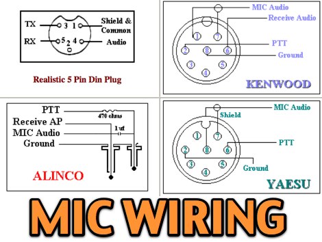 11 most popular MIC wiring diagrams including AZDEN Alinco Icom Kenwood Yaesu Astatic Cobra Sadelta Turner microphens diagrams and pin-end views
 -
 Microphone wiring can be a pain if your not sure how to work out which wire goes where
 -
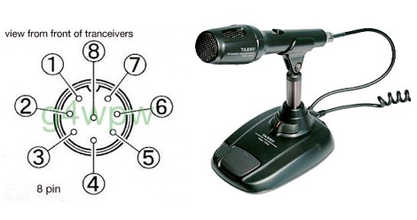 Yaesu MD-100 microphone schematic wire diagram with pin out
 -
 This online guide details the microphone pinout for the Kenwood TR-7950 transceiver, specifically addressing the wiring configuration for a dynamic mobile microphone with a **500 Ohm** impedance. It provides a pin-by-pin breakdown for the 6-pin microphone connector, identifying the function of each active pin. The resource specifies that Pin #1 is for the microphone audio (white wire), Pin #2 controls the _PTT_ (black wire), Pin #3 activates the memory down function (blue wire), and Pin #4 controls the memory up function (red wire). Pin #6 is designated as the ground connection, while Pin #5 remains unused in this configuration. The document focuses on the physical wiring necessary to restore microphone functionality to the Kenwood TR-7950, a transceiver capable of **45 watts** output on the _2m band_. It directly addresses the technical challenge of re-establishing correct electrical connections after microphone wires have been disconnected from the connector. The information facilitates proper microphone operation for simplex QSOs and other voice communications. DXZone Focus: Online Guide | Microphone Pinout | Kenwood TR-7950 | PTT Wiring
 -
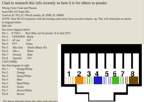 Wiring Color Code and Pinouts for IC-706MkIIG and HM-103 Mic
 -
 The m0xpd keyer project utilizes a PIC16F628A microcontroller, offering Iambic A and B modes, adjustable speed from 5 to 40 WPM, and variable weight control. It incorporates a sidetone generator with adjustable frequency and volume, along with a PTT output for transceiver control. The design includes a 16-pin DIL IC socket for the PIC, a 3.5mm stereo jack for the paddle, and a 3.5mm mono jack for the PTT output. Powering the keyer requires a 9V DC supply, which is regulated down to 5V for the PIC. The circuit board layout is designed for through-hole components, facilitating home construction. A detailed schematic and a parts list are provided, guiding builders through the assembly process. The project also discusses the firmware programming for the PIC16F628A, essential for the keyer's functionality. Construction details cover component placement and wiring, ensuring proper operation. The keyer's compact size makes it suitable for portable or shack use, providing a reliable CW interface.
 -
 Operating the _Icom IC-746_ HF/VHF transceiver often presents specific technical questions, and this resource compiles a comprehensive Frequently Asked Questions (FAQ) document in an ASCII text format. It details common inquiries and solutions related to the rig's functionality, accessories, and potential modifications. The content is structured into distinct sections addressing general information, power supplies, antennas, microphones, keyers, amplifiers, TNC integration, and optional IF filters. The FAQ provides practical guidance on topics such as configuring the internal automatic antenna tuning unit (ATU), selecting appropriate power supplies, and understanding microphone pin-outs. It also delves into advanced subjects like computer control via CI-V, wiring for PSK31 operation, and troubleshooting common issues like low S-meter readings on 2m FM or loose tuning shafts. Specific questions cover the installation of optional IF filters, comparing Inrad versus Icom filters, and optimizing filter combinations for various modes. Furthermore, the document outlines various hardware and firmware modifications, including those for increasing monitor volume, replacing LCD driver transistors, and implementing a "poor man's TCXO." It even touches upon untested modifications, such as replacing PIN diodes in the demodulator. The FAQ also lists manual errata and discrepancies, offering a robust knowledge base for IC-746 owners seeking to optimize their station or resolve operational challenges.
 -
 Constructing a digital interface for the Elecraft K2 transceiver, this resource details the "Fat Wire" design by WG4S. It demonstrates how to integrate a sound card for digital modes, outlining specific connections to the K2's microphone jack and internal audio path. The author shares practical insights from his build, including the use of _RG-62_ coax for its flexible braid and the strategic placement of components like the 2.2K resistor and _2N2222_ transistor. The guide provides a breakdown of the interface's internal wiring, specifying connections for AF In (pin 1), AF Out (pin 5), PTT (pin 2), and Ground (pin 7) on the K2's microphone connector. It also covers the external connections to a laptop's headphone and line-in jacks, along with a DB-9 connector for PTT control via _DTR_ or RTS lines. The author notes that his laptop's headphone output level was sufficient for the K2, negating the need for an attenuator. Reflecting on the design, the author, Dan WG4S, acknowledges a later suggestion to house the components directly within the DB-9 shell for a more compact build. This iterative feedback highlights the ongoing evolution of DIY ham radio projects and the community's collaborative spirit in refining designs.
 -
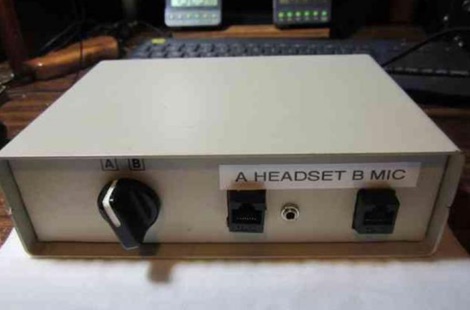 A 15-pin data switch, typically a rotary-knob type designed for DB-25 connectors, forms the basis for this microphone selector project. The resource details the conversion process, which involves replacing the original DB-25 connectors with **RJ-45** or **RJ-12** jacks to accommodate modern amateur radio microphones. It specifically addresses wiring for radios like the Icom IC-706 series (including the IC-7000 and IC-703) and Yaesu transceivers such as the FT-857, FT-897, FT-817, FT-7800, FT-7900, FT-8800, FT-8900, FTM-100, and FTM-400. The design ensures all microphone lines are switched straight through, with separate contacts for external speaker/headphone jacks, allowing simultaneous switching. The project emphasizes the practical application of switching between a headset for net control and a hand mic for rag-chewing without repeatedly plugging and unplugging cables. It highlights modifications to the original concept, such as eliminating a separate PTT jack by integrating PTT into headset cables and building the external speaker cable directly into the selector. The article provides guidance on managing the non-color-coded wiring often found in these data switches by soldering wires one by one from old to new connectors, ensuring correct pin alignment. This approach simplifies the conversion, making it accessible for hams seeking a functional and cost-effective mic switching solution.
 -
 This Arduino project explores long-range RF communication using EBYTE E32 1W LoRa modules (either E32-915T30D or E32-900T30D) paired with ESP32 microcontrollers featuring OLED displays. The setup leverages the modules' Semtech SX1276 chip with amplifier to achieve up to 1W transmission power—significantly more than the chip alone provides. Unlike other LoRa implementations, these modules include a microcontroller that simplifies interface through UART rather than SPI. The documented implementation includes proper wiring between components and Arduino code that configures the module, displays received messages on the OLED screen, and transmits messages every two seconds while keeping power consumption manageable.