Search results
Query: 80 40 15 meters
Links: 44 | Categories: 0
-
 An Attic Coaxial-Cable trap dipole for 10, 15, 20, 30, 40, and 80 meters
 -
 Home made vertical antenna for 80 40 15 10 meters ARRL PDF file taken from QST June 1978
 -
 The G5RV antenna, with an overall length of **31.10m (102ft)**, functions as a 3/2-wave on 20 meters when installed horizontally at 12m (39ft), exhibiting a resonant frequency of 14.150MHz and an approximate resistance of 80 ohms. Its 10.36m (34ft) stub line, designed as a 1/2-wave on 14.150MHz with a 0.97 velocity coefficient, acts as an impedance transformer across other bands, aiming for multiband operation without traps. On 20m and higher frequencies, the G5RV demonstrates improved gain compared to a standard dipole, attributed to the _collinear effect_ from multiple 1/2-waves along the wire. The original design sought a multiband solution for limited spaces, often requiring an Antenna Tuning Unit (ATU) for effective operation across bands like 80, 40, 30, and 20m, particularly with modern solid-state PAs. Variants, such as the F8CI modification, incorporate a 1/4 current balun at the stub line's base for symmetrical-to-asymmetrical transition, known as a _remote balun_. Proper flat-top or inverted-V installation is critical for maintaining symmetry and collinear gain, with inverted-V apex angles below 120° progressively diminishing higher-band performance.
 -
 A multiband 80-40-20-15 meters dipole wire antenna that can be extended to cover 160 meters too.
 -
 Demonstrates the construction of **magnetic loop antennas**, detailing both multi-turn and single-turn designs. It covers a 30-inch diameter multi-turn loop for 80 meters, based on a February 1996 QST article, and an octagon single-turn loop made from 15mm copper tube with a 4.8-meter circumference, operating from 7 MHz to 14 MHz. The document also presents a smaller 800mm diameter loop for 14 MHz to 28 MHz, emphasizing the importance of high-voltage tuning capacitors. Covers the design and construction of custom **butterfly capacitors** and piston capacitors, including a split stator capacitor with 140 pF capacitance and a 6000 Volt rating, and a butterfly capacitor with 5-65 pF and 7200 Volt rating. It explains why butterfly capacitors are preferred over split stator types for high power applications due to lower losses and direct series connection of rotors, reducing resistive losses from wiper contacts. Material recommendations include clear PVC for plates and brass or stainless steel for non-magnetic hardware. Addresses practical considerations such as feeding the loop with a shielded 1/5 Faraday loop made from RG213 or RG8 coax, achieving VSWR 1.1 across bands, and optimizing its placement 180° from the capacitor. It also discusses mechanical joint resistance, dissimilar metal oxidation prevention using Vaseline, and a simple method for determining radiation angle with a TL-light tube. The guide includes diagrams for rotor, stator, and end plate construction.
 -
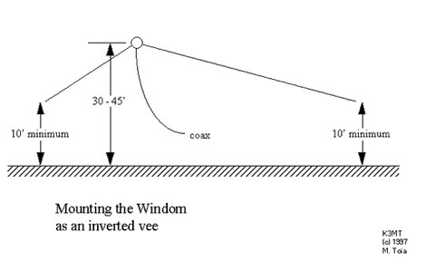 HF Windom antenna, cover 80, 40, 20 15, and 10 meters, antenna design
 -
 Build your own multiband W3DZZ antenna resonating on 80 40 20 15 and 10 meters band
 -
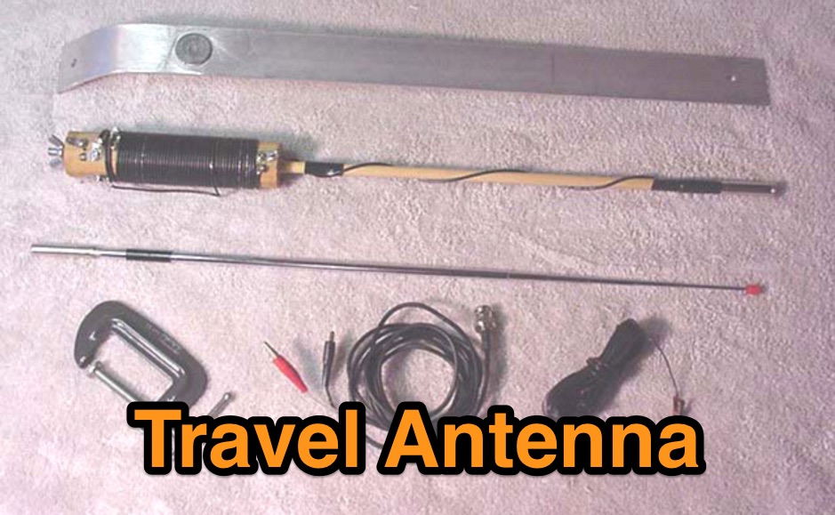 This is a low cost homebrew two band travel antenna for 20 and 40 meters. It is based on the B&W Travel Antenna concept with a telescoping whip and a loading coil
 -
 The 80-meter loop antenna, measuring 86 meters (282 feet) of wire, effectively operates across 8 HF bands from 80 through 10 meters, despite its length being a compromise for specific bands. This design prioritizes a "low enough" SWR across multiple bands, aiming for lower SWR values on higher frequencies due to increased feedline losses. A 200-ohm feedpoint impedance provides a workable SWR on every band, with feedpoint impedances ranging from 100 ohms for lower bands to 300 ohms for higher bands. Radiation patterns for the 80-meter loop, mounted at 15 meters high, show a maximum gain of 7.6 dBi at a 90-degree takeoff angle on 80 meters, and up to 12.9 dBi at a 10-degree takeoff angle on 12 meters. This configuration supports regional contacts on 80 meters and provides good DX performance on higher bands. Practical construction notes emphasize using robust supports like trees, ensuring wire slack with _egg insulators_ for wind resilience, and employing an oversized 2 kW 4:1 _balun_ to safely handle higher SWR conditions, even with 100W transceivers. Feedline losses are minimized using _LMR-400_ coax or ladder line, with power transfer efficiency between 80% and 95%. Antenna simulations were performed using _xnec2c_, and the provided NEC file is compatible with other NEC2 derivatives. The antenna is tunable on 6 of 8 bands with an internal ATU and all 8 bands with an external autotuner like the LDG AT-200 Pro.
 -
 The Bruce array is a simple, often-forgotten wire antenna array that is advantageous for 80 and 160 meters, where typical gain antennas are very large. This bi-directional broadside vertical array is only 1\4 lambda high and does not require a ground system. It offers substantially greater SWR bandwidth than the half-square or bobtail curtain. A 4-element Bruce array used by N6LF showed a gain of about 4.6 dB compared to a 1\4 lambda vertical with 8 elevated radials, with a 2:1 SWR bandwidth greater than 400 kHz. The antenna is simple and its dimensions are flexible.
 -
 Multiband Center-Loaded Off-Center-Fed Dipole (CL-OCFD) antenna that work on 80m 40m 30m 20m 15m 10m. The Center-Loaded Off-Center-Fed Dipole (CL-OCFD) antenna, developed by Serge Stroobandt, offers a versatile solution for amateur radio enthusiasts, covering multiple HF bands (80, 40, 30, 20, 15, and 10 meters) without the need for an antenna tuner. This innovative design utilizes a capacitor for resonance on the 80-meter band and a resistor to manage static charges. The CL-OCFD enhances bandwidth and simplifies operation, making it a significant advancement on OCF Dipole design.
 -
 Wire antenna for 10-15-20-40-80 meters band, with many drawings and description in spanish
 -
 The ZS6BKW multiband HF antenna, a design by ZS6BKW (G0GSF), functions effectively on multiple HF bands without requiring an Antenna Tuning Unit (ATU) for 40, 20, 17, 12, 10, and 6 meters. This antenna, approximately **27.51 meters** (90 feet) long with a 12.2-meter (40-foot) open-wire feeder, is a direct descendant of the _G5RV_ but offers superior multi-band resonance. It can be deployed as a horizontal dipole or an inverted-vee, with the latter requiring only a single support and maintaining an apex angle of at least 90 degrees to prevent signal cancellation. Performance data, recorded with an MFJ Antenna Analyser, indicates SWR values of 1:1 on 7.00 MHz (40m) and 14.06 MHz (20m), with SWR below 1.3:1 on 17m, 10m, and 6m. While primarily designed for these bands, the antenna can be adapted for 80m, 30m, and 15m with an ATU, preferably at the balanced feeder's base. The use of 450-ohm twin-lead for the feeder is recommended over 300-ohm for improved strength and reduced losses, especially in adverse weather conditions. This design, originally published in _RadCom_ in 1993 and featured in Pat Hawker’s "Antenna Topics," provides a compact and efficient solution for HF operation, particularly for those with limited space or resources.
 -
 A multiband antenna that can work from 80 to 10 meters in this illustrated docuemnt by G8ODE
 -
 This is a popular antenna design as the performance is very good across the HF bands and requires little or no tuning. It is a dipole fed off center with a 4:1 current balun at the offset feedpoint. The antenna shown covers 80, 40, 20 and 10 meters with 15 meters and WARC bands
 -
 An 87ft inverted L portable antenna working on 80 40 30 20 15 meters band
 -
 Operating a ZS6BKW antenna often involves understanding its lineage from the _G5RV_ design, with specific modifications by ZS6BKW to optimize performance on several bands. Through computational analysis and field measurements, the antenna's dimensions were refined to allow operation on 10, 12, 17, 20, and 40 meters without an antenna tuner. For 80, 30, and 15 meters, a tuner is necessary, though efficiency on 30 and 15 meters is noted as not particularly high. The physical configuration consists of two 13.755-meter radiating elements fed by a 12.20-meter section of 450-ohm ladder line. Tuning the antenna on the 20-meter band is critical, and any deviation in the ladder line's characteristic impedance necessitates recalculating the element lengths. The design is also referenced in the 12th edition of _Rothammel's Antennenbuch_, page 219. Proper common mode current suppression is crucial at the transition from ladder line to coaxial cable. This can be achieved with a common mode choke, such as several turns of coax wound into a coil or over a ferrite toroid like an Amidon T130. While a 1:1 balun is an option, it may introduce issues.
 -
 A simple 7 bands off-center dipole wire antenna designed to work on 80 meters band and that can cover also 40m 30m 20m 15m 12m 10m with acceptable SWR
 -
 The ZS6BKW antenna, a popular multiband wire antenna, offers improved band matching compared to the traditional G5RV. This construction guide details the process, beginning with specific dimensions: 13.11 meters (43 feet) for the 450-ohm ladder line and initial dipole arm lengths of approximately 14.8 meters each. It emphasizes the critical role of an _antenna analyzer_ for accurate tuning, particularly for determining the velocity factor of the ladder line and achieving a 1:1 impedance match. The article outlines the materials required, including a 1:1 current balun, 450-ohm window line, wire for the dipole arms, and a 50-ohm non-inductive resistor for testing. It provides a step-by-step procedure for cutting the ladder line to its electrical half-wavelength, explaining how to calculate the velocity factor using measured and free-space frequencies. For instance, a measured 50-ohm impedance at 12.54 MHz with a calculated free-space half-wavelength frequency of 11.44 MHz yields a velocity factor of 0.91. Final adjustments involve hoisting the antenna to its operational height and fine-tuning the dipole arm lengths to achieve optimal SWR, specifically targeting 14.200 MHz. The _ZS6BKW_ design is noted for its performance on 80m, 40m, 20m, 10m, and 6m, though it is not optimized for 15m operation. The author, _VK4MDX_, shares practical tips for durable construction using stainless steel wire and cable clamps.
 -
 The Vee Beam antenna project presents a versatile solution for hams, enabling operation across all eight High Frequency bands (80m to 10m) with significant gain on 20m to 10m. This easy-to-construct antenna utilizes two long wires at an angle, enhancing directional performance and minimizing ground losses. With a low visual profile, it is discreet and effective for various applications. The design allows for optimal leg lengths and included angles, ensuring robust performance while maintaining simplicity in construction and operation. The V Beam antenna is an aerial that you can use on all eight High Frequency amateur bands (80, 40, 30, 20, 17, 15, 12 and 10m) with an antenna tuner, and which gives significant gain on the five bands from 20 to 10 meters band.
 -
 An Off-center-feed antenna that covers 80, 40, 20, 17, 15, 12, 10, and 6 meters
 -
 A simple RF power amplifier initially designed for 40 meter band can work on 10 15 20 40 80 meters
 -
 A trapped dipole antenna based on the orignal W3DZZ antenna design resonating on 80 40 20 15 10 meters
 -
 Extension to an existing fan dipole originally modeled for 40 20 and 6 meters. This modification will add 80 15 and 10 meter bands.
 -
 Optimizing a G5RV or ZS6BKW multiband wire antenna for HF operation often involves addressing common SWR issues and understanding feedline characteristics. This resource chronicles the construction and performance evaluation of a G5RV, initially built for 80m, 40m, 15m, and 10m bands, by a newly licensed Foundation operator. The author details the selection of materials, including 3.5 mm stainless steel wire for the doublet arms and enameled copper wire for the open-wire feeder, and the initial decision to omit a balun based on common online information. The narrative highlights the initial disappointing performance, characterized by high receive noise and poor signal reports on 80 meters, despite the transceiver's internal ATU achieving a 1:1 match. This led to experimentation with a coax current balun and further research into G5RV myths, such as SWR claims and the necessity of a balun. The author then describes modifying the antenna to the ZS6BKW configuration, which involves specific changes to the doublet and feedline lengths, and integrating a 1:1 current balun wound on a ferrite toroid. The modifications resulted in improved reception and transmit performance across the bands.
 -
 The ZS6BKW multiband antenna, an optimized variant of the classic G5RV, features a 102-foot (31.1 m) horizontal span and a 39.1-foot ladder line matching section. This design, derived by G0GSF (formerly ZS6BKW) in the early 1980s using computer programs and _Smith charts_, aims for improved SWR across multiple HF bands compared to its predecessor. Construction details specify Wireman 554 ladder line and #14 AWG THHN copper wire for the radiators, with precise instructions for determining the velocity factor (VF) of the ladder line using an antenna analyzer or dip meter, ensuring accurate physical length for the matching section. The radiator length is electrically 1.35 wavelengths for the 20-meter band, requiring careful trimming during tuning. Field measurements with an _AIM-4170C_ analyzer by KI4PMI and NC4FB demonstrated good SWR curves and bandwidth on 6, 10, 12, 17, 20, and 40 meters. The antenna was deemed unusable on 15 and 30 meters due to very high SWR, but an LDG AT-100PRO autotuner successfully brought 6 and 80 meters into tune. Contacts were made on 80, 40, 20, and 17 meters, including a **17-meter** contact to Spain. EZNEC models for 80-6 meters are provided, along with an AutoEZ model by AC6LA, which predicted good SWR for 80-10 meters. W5DXP's modifications for an all-band HF ZS6BKW are also referenced.
 -
 The X80 multi-band HF vertical antenna, a commercial iteration of the Rybakov design, exhibits a physical length of 5.5 meters, or approximately 18 feet, and is constructed from aluminum tubing. It operates as a non-resonant vertical, requiring an external antenna tuner for impedance matching across its intended operating frequencies. The antenna's design incorporates a 1:4 UNUN at its base, facilitating a nominal 50-ohm feed point impedance for the coaxial cable. Performance observations indicate effective operation on 40 meters, 20 meters, 15 meters, and 10 meters, with reduced efficiency on 80 meters and 160 meters due to its relatively short electrical length for these lower bands. Comparative analysis with a G5RV dipole and a half-wave end-fed antenna reveals the X80 offers a lower take-off angle, beneficial for DX contacts, particularly on the higher HF bands. Field tests conducted with an Icom IC-706MKIIG transceiver and an LDG AT-100ProII autotuner demonstrate the X80's ability to achieve acceptable SWR across 80m through 10m. The antenna's compact footprint and ease of deployment make it suitable for restricted spaces or portable operations, though its performance on 80 meters is noted as a compromise compared to full-size resonant antennas.
 -
 The ZS6BKW multi-band antenna, an optimized variant of the classic G5RV, is presented with detailed construction and tuning instructions. This resource outlines the antenna's design principles, which were developed by _Brian Austin (G0GSF)_ using computer programs and Smith charts to achieve optimal dimensions. It provides specific guidance on calculating and adjusting the lengths of the radiators (L1) and the matching ladder line (L2), emphasizing the critical role of velocity factor (VF) in achieving resonance. The article includes a step-by-step procedure for empirically determining the VF of ladder line using an antenna analyzer, ensuring accurate physical lengths for the matching section. It details the tuning process for the radiators, offering practical tips for incremental adjustments to achieve the best SWR curve. The resource presents SWR measurement results obtained with an _AIM-4170C_ analyzer across multiple bands, alongside predicted SWR graphs from an AutoEZ model. It confirms successful contacts on 80, 40, 20, and 17 meters, including a **17-meter DX contact** to Italy. EZNEC and AutoEZ models for the ZS6BKW antenna, covering 80 through 6 meters, are provided for download, allowing further analysis and customization. The document specifies component details, such as the use of Wireman 554 ladder line and #14 AWG THHN copper wire, and discusses the antenna's performance characteristics, noting high SWR on 15 and 30 meters but successful tuning on 6 and 80 meters with an external tuner.
 -
 Amateur Radio 40m 20m 15m Half Wave Fan dipole antenna project with part list, pictures and drawing. Includes the option to expand the antenna to cover the 80 meters band
 -
 Local amateur radio clubs often serve as vital hubs for hams to connect, share knowledge, and participate in group activities. The Orleans County Amateur Radio Club (OCARC), operating under the callsign WA2DQL, provides a focal point for amateur radio operators in Albion, New York, and the surrounding Orleans County area. These organizations frequently host events, offer technical assistance, and foster camaraderie among members, supporting various aspects of the hobby from contesting to emergency communications. OCARC's activities include discussions on proposed Technician class privileges for **80, 40, and 15 meters**, indicating an interest in regulatory changes affecting entry-level licensees. The club also promotes the use of online tools like _Radio Mobile Online_ for antenna pattern analysis and _VOACAP Online_ for propagation predictions, aiding members in optimizing their station performance. Furthermore, OCARC highlights participation in _Parks On The Air_ (POTA) events, such as the Erie Canal Bicentennial Celebration in 2025, encouraging outdoor operations and public engagement with amateur radio.
 -
 A dual band portable inverted V antenna for 80 and 40 meters band with dimensions for other bands and several assembling instruction
 -
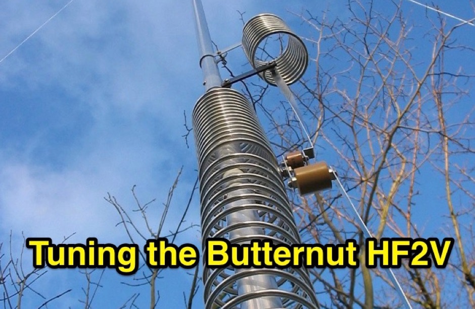 Complete instructions on tuning the Butternut HF2V on four bands, 80, 40 , 30 and 15 meters
 -
 Presents a concise guide for Amateur Radio operators participating in Jamboree-on-the-Air (JOTA), an annual event connecting approximately 500,000 Scouts and Guides worldwide via ham radio. The resource details how to initiate a voice contact, including the use of "CQ Jamboree JOTA" and proper signal reporting with the RST system. It also outlines the typical exchange information, such as name, QTH, Scout rank, and age, encouraging participants to practice their responses. Authored by Bill Wetherill, N2WG, the brochure provides a practical phonetics chart and a comprehensive Morse code dictionary, including punctuation and prosigns like AR and SK. It clarifies rules for third-party operation under the direct supervision of a licensed operator, noting restrictions on international contacts without specific government agreements. Additionally, the guide lists recommended World Scout Frequencies for SSB and CW across 80, 40, 20, 17, 15, 12, and 10 meters, emphasizing courteous operating procedures. It includes a section on common Q-signals like QRM, QRN, and QSL, alongside the Amateur's Code, which stresses considerate, loyal, progressive, friendly, balanced, and patriotic conduct.
 -
 A loop antenna for 80 and 40 meters band, the main loop is based by a crossed line using aluminium strip lines. The main loop diameter is 150 cm.
 -
 Low-frequency (LF) radio time signals, operating primarily in the 40–80 kHz range, are broadcast by national physics laboratories for precise clock synchronization. Transmitters like **JJY** (40 kHz, 50 kW; 60 kHz, 50 kW), RTZ (50 kHz, 10 kW ERP), MSF (60 kHz, 15 kW ERP), WWVB (60 kHz, 50 kW ERP), RBU (66.66 kHz, 10 kW), and DCF77 (77.5 kHz, 50 kW) cover vast geographic areas, often several hundred to thousands of kilometers. LF signals offer distinct propagation advantages over higher-band transmissions such as GPS. Their long wavelengths (3–6 km) enable effective diffraction around obstacles like mountains and buildings. The ionosphere and ground act as a waveguide, eliminating the need for line-of-sight and allowing a single powerful station to cover extensive regions. Ground wave propagation minimizes ionospheric variability effects on transmission delay, and signals penetrate most building walls effectively. Robust and low-cost receivers, often priced at 20–30 USD/EUR, are widely used in radio clocks. These receivers typically comprise a tuned ferrite core antenna, a receiver IC (e.g., Atmel T4227, U4223B, MAS1016) for amplification and AM detection, and a microcontroller for decoding the time signal and phase-locking a local clock. Specific components for DCF77, MSF, and WWVB are readily available from vendors like HKW Elektronik and Ultralink.
 -
 A 60-foot available space, for example, might necessitate a shortened multiband dipole array to cover 80, 40, and 15 meters effectively. This resource details the construction of such an antenna, combining full-size and coil-loaded dipoles on a single feedline. It addresses the common challenge of fitting multiple HF bands into restricted physical footprints, providing practical guidance for hams with smaller backyards or portable operations. The core of the offering is an interactive calculator that determines required loading coil inductance and dipole lengths for various amateur bands from 160m to 10m. Users input their available space, and the tool provides dimensions, coil turns, and an efficiency rating (Good or Fair) based on the antenna's electrical length relative to a quarter-wavelength. It also suggests suitable _PVC_ pipe diameters for coil forms. The article further illustrates a center feed-point assembly using an 18-inch section of 2-inch _PVC_ pipe, detailing eye-bolt spacing and coaxial connector installation. It emphasizes the importance of adequate spacing between parallel dipoles and offers customization options for the feed-point, including the addition of a _Balun_ for improved feedline isolation.
 -
 With this antenna the coverage is 80,40,20,15 and 10 meter band without any antenna tuner and the average SWR is below 1.2 on phone bands. The total antenna lenght is about 23 meters , with one 20.4 meters long segment from the 1:49 transformer to the 110uh coil and about 2.2 meters long segment from the coil to the insulator.
 -
 Vertical end fed antenna used for portable operations. The antenna will work on 80 with acceptable results, it will work fine on 40m, and it will be a good deal better than a normal 1/4 wave GP on 20, 17, 15 meters.
 -
 WebSDR Pardinho SP Brazil providing access to HF bands 160 80 40 20 15 11 meters bands.
 -
 A home made portable QRP transceiver designed to work on 40 or 80 meters SSB band.
 -
 This antenna is designed for 40, 80 and 160 meters to complement a tri-band beam normally taken on DX peditions for 10, 15 and 20 meters, so six bands can be worked with only two antennas.
 -
 The tri-band trapped delta loop antenna design operates on 80 meters (3.5–4 MHz), 40 meters (7–7.3 MHz), and 30 meters (10.1–10.15 MHz) using a single triangular wire loop. This configuration eliminates the need for an external antenna tuner or band-switching relays. The antenna's physical perimeter, approximately 270 feet, establishes 80M as the fundamental band, with specific trap placements enabling resonance on 40M and 30M. Trap design and placement are critical, with 30M traps positioned inboard of 40M traps within the horizontal element. Each slant leg measures approximately 80 feet. The resource references foundational information from the _ARRL Antenna Handbook_ and _ON4UN’s Low Band DXing_ regarding full-wave loop behavior and feedpoint impedances. The project aims to provide multi-band HF operation from a single, fixed antenna structure.
 -
 Presents DJ5IL's personal amateur radio station, detailing his journey as a licensed operator since 1973. The resource covers his **shack setup**, including an Elecraft K4D, Icom IC-7610, and various vintage transceivers like the Drake 2-B, along with a SPE Expert 1K-FA amplifier. Antenna systems include a PRO.SIS.TEL RD1524T rotary dipole for 40/20/15/10m at 15m height, an 18m vertical dipole with an SGC SG-230 tuner for 3.5-30 MHz, and an inverted-V dipole for 80m. The site features a **QSL gallery** showcasing his custom card designs and outlines his QSL policy, emphasizing the exchange of unique, personalized cards over generic confirmations. It also includes a detailed operator's biography, tracing his early fascination with radio, obtaining his license at 16, and memorable QSOs, such as a contact with his blood-relative W3NZ. The resource also delves into the historical significance of amateur radio's role in pioneering shortwave communication following the 1912 International Radiotelegraph Convention, which initially relegated amateurs to wavelengths of 200 meters and shorter. DJ5IL's philosophy on "ham spirit" is discussed, stressing the unpolitical nature of amateur radio as a global fraternity.
 -
 VE1ZAC's analysis details the performance of **MFJ927** and **SGC239** autotuners with portable HF vertical antennas, specifically comparing 31 ft and 43 ft configurations. The resource originated from challenges encountered during a Maritime QSO Party roving operation, necessitating a lightweight and easily deployable antenna system. Target bands for the contest included 80, 40, 20, 15, and 10 meters, with a maximum power handling of 100 W CW. The author utilized a 30-foot carbon fiber push-up pole to support a vertical wire element, noting its 2 lb weight and reliability. EZNEC modeling was employed to predict performance, showing favorable results for a 30-foot vertical with elevated radials, particularly on 40 and 20 meters. Feedpoint impedance measurements, taken with an AIM4170C, are presented for various HF bands, both with and without a 41-foot RG6 stub designed to reduce reactance on 80 and 20 meters. The stub significantly improved matching on these bands, easing the tuner's workload. Operational tests revealed issues with the MFJ927's reliability during contest setup, leading to reliance on the K3's internal tuner. The SGC239, tested post-contest, performed flawlessly. A detailed side-by-side comparison covers mechanical aspects, connection options, power bias, impedance range, board quality, and documentation. Modifications to the MFJ927, including a new aluminum case, white paint for heat reduction, and upgraded impedance-measuring resistors, are also described.