Search results
Query: multi band trap dipole
Links: 25 | Categories: 1
Categories
-
 The G5RV antenna, with an overall length of **31.10m (102ft)**, functions as a 3/2-wave on 20 meters when installed horizontally at 12m (39ft), exhibiting a resonant frequency of 14.150MHz and an approximate resistance of 80 ohms. Its 10.36m (34ft) stub line, designed as a 1/2-wave on 14.150MHz with a 0.97 velocity coefficient, acts as an impedance transformer across other bands, aiming for multiband operation without traps. On 20m and higher frequencies, the G5RV demonstrates improved gain compared to a standard dipole, attributed to the _collinear effect_ from multiple 1/2-waves along the wire. The original design sought a multiband solution for limited spaces, often requiring an Antenna Tuning Unit (ATU) for effective operation across bands like 80, 40, 30, and 20m, particularly with modern solid-state PAs. Variants, such as the F8CI modification, incorporate a 1/4 current balun at the stub line's base for symmetrical-to-asymmetrical transition, known as a _remote balun_. Proper flat-top or inverted-V installation is critical for maintaining symmetry and collinear gain, with inverted-V apex angles below 120° progressively diminishing higher-band performance.
 -
 The multi-band trapped dipole is resonant on approx 3.7, 7, 14, 24 7 28.5 Mhz. The overall top length needs to be approximately 32.9 Meters
 -
 This improved multiband trap dipole introduces a new trap design and a change in trap location. The antenna features double-coaxial-cable-wound traps having lower reactance and a higher quality factor (Q) than earlier coax-cable traps by W8NX
 -
 A rotary trapped-dipole for 17 and 20 meters, as described by IZ7ATH, presents a practical solution for multi-band HF operation. The author, Talino, recounts his experience building this antenna for IK7ZCQ, detailing the evolution from an initial concept involving a grounded-driven element and gamma-match to a direct-fed, non-grounded design. His pragmatic approach, adapting available materials, is evident throughout the construction narrative, particularly with the use of eight tapered aluminum pipes for the driven element. Construction specifics include precise measurements for the aluminum tubing, with diameters ranging from 30 mm down to 16 mm, and a critical note on reducing tip thickness for weight optimization. The _traps_, initially a concern, are fabricated using 8 turns of RG58 coax on a 27 mm support, tuned to resonate at 18.1 MHz using a dip-meter. Talino emphasizes sealing the traps with RF glue and PVC tape to prevent water ingress, a crucial step for longevity. Field test results, conducted on a 10-meter pole in a clear garden environment, showed an SWR of 1.2:1 on 17 meters and 1.5:1 at 14.200 MHz. While SWR varied slightly when installed at Mario's QTH due to nearby objects, the antenna's performance remained commendable. The final half-dipole length is 46 cm for the 18 MHz tips, and the total weight is under 6 kg, with potential for further reduction.
 -
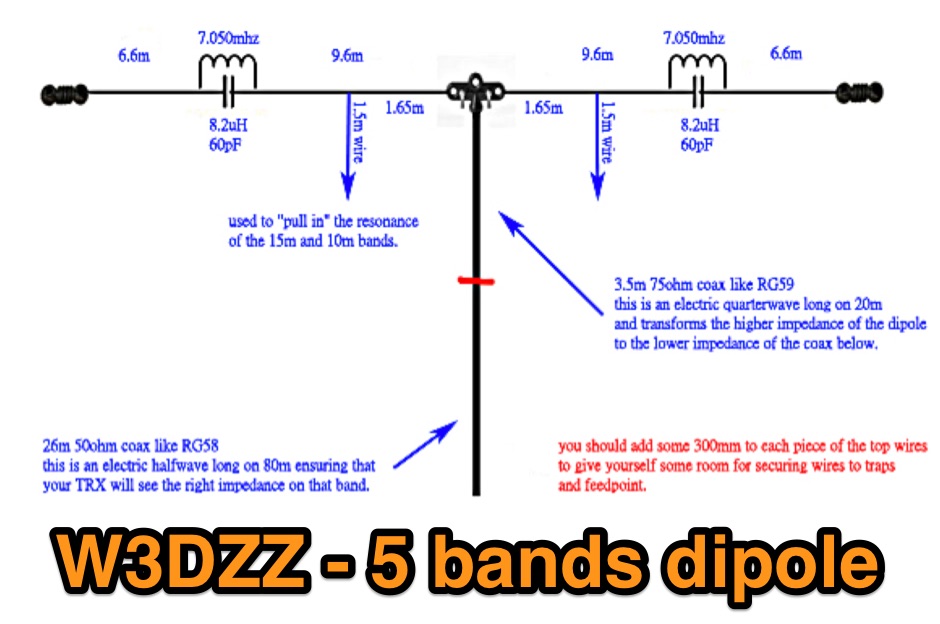
 The W3DZZ trap dipole is a versatile and economical antenna option for amateur radio operators looking to work multiple bands without the need for extensive equipment. This antenna design utilizes traps to allow operation on various HF bands, making it suitable for both casual operators and serious DXers. Its construction is straightforward, making it accessible for beginners while still providing excellent performance for seasoned hams. Constructed with readily available materials, the W3DZZ trap dipole can be built to fit specific band requirements, allowing operators to optimize their setup for the frequencies they intend to use. The design is particularly favored for its ability to maintain a low profile while delivering effective radiation patterns. Whether you're contesting or chasing DX, this antenna can enhance your station's capabilities without breaking the bank.
 -
 Video construction of a multiband HF trapped dipole antenna based on a variation of the classic W3DZZ design
 -

-
 An easy to build multiband trapped dipole that can work well on short low bands for skip contacts
 -
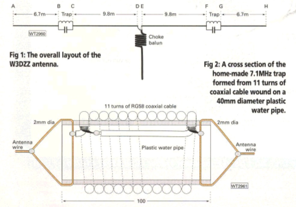 W3DZZ trapped multi-band antenna, exposed in this practical wireless article
 -
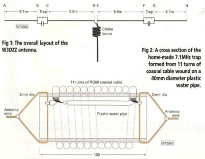 Article published on Practical Wireless about the W3DZZ multiband trapped dipole antenna made available by GM0ONX
 -
 This project details the construction of a **full-sized 40-meter vertical antenna**, born from a renewed interest in 7 MHz operation and a desire for improved effectiveness over simple dipoles. The author, K5DKZ, initially focused on VHF experimentation, which provided an inventory of aluminum tubing and fiberglass spreaders for this endeavor. Before this vertical, K5DKZ utilized an 80/40 meter inverted-vee trap dipole and a 40-meter broadband dipole, but now primarily uses a pair of full-sized, phased, quarter-wave verticals spaced 35 feet apart for serious 40-meter work. The construction involves a base-heavy design for stability, using a 44.5-inch section of 1-1/4 inch steel TV mast driven into 1-3/8 inch aluminum tubing, insulated by a 105-inch section of Schedule 40 PVC pipe. The assembly reaches 31 feet, close to the 32 feet required for a quarter-wavelength on 40 meters, with fine-tuning achieved by winding wire onto a fiberglass spreader. The design is explicitly presented as a foundation for a two-element 40-meter Yagi beam, outlining modifications like substituting aluminum for steel in the base and using an inductive hairpin match for the driven element. The article also discusses tuning considerations for a large 40-meter beam, noting the 100 to 200 kHz upward frequency shift when raised, and suggesting methods for installation on a tower. The author emphasizes the cost-effectiveness and good performance of the monopole approach, especially when multiple verticals are needed.
 -
 Presentation by AC8GY on classic G5RV Antennas and other horizontal dipoles, the popular G5RV, ZS6BKW, dipole fan, Alpha-Delta DX-CC and a trap dipole are modeled in EZNEC and compared.
 -
 A multiband coax trapped dipole for 10-80 meters bands by DF1PU
 -
 The resource details the construction of a multiband trap-style Inverted-V antenna designed for operation on 3.5 MHz, 7 MHz, 14 MHz, 21 MHz, and 28 MHz. It presents specific winding data for the traps, including the number of turns, wire gauge, and coil former dimensions, crucial for achieving resonance on the target bands. The document provides a parts list and a diagram illustrating the antenna's physical layout and trap placement. It outlines the process for building the traps using PVC pipe formers and specifies the required capacitor values for each trap. The design emphasizes a practical approach to achieving multiband operation with a single feedline, a common goal for HF operators with limited space. The document includes a table with antenna segment lengths for each band, allowing for precise replication of the design. It also offers insights into tuning and adjustment, ensuring the antenna performs optimally across the designated amateur radio bands.
 -

-
 An easy to build and extremely high performance antenna, works perfectly on all HF bands 3.5-28 MHz with some compromises, it is basically an half wave dipole for 40-80 meters, an LC circuit or trap 40 meters allows you to use a single radiating element.
 -
 Multiband Trap Dipole, portable short antennas, accessories and kits by DG1DBM
 -

-
 This antenna is a classical antenna working on 7,10,14,18,50 MHz is implemented with three traps for 30, 17 and 6 meters
 -
 Discovering a solution for limited space, the inverted L HF antenna emerges as a stellar performer. Half the size of a dipole, it ensures optimal installation in restricted areas, maintaining superb transmission (TX) and reception (RX) characteristics. Spectrum Communications' multi-band version, featuring traps, proves even more space-friendly without compromising performance. A fiberglass pole offers sturdy support, while proper grounding, an RF choke, and occasional tuning contribute to a high-performing and reliable antenna system.
 -
 This article describes a multi-band antenna design for amateur radio enthusiasts by G3FEW. The antenna is designed to cover at least five HF bands with low SWR and without the need for an ATU. It is also designed to be easy to construct and adaptable for different locations. The antenna is a full-wave dipole with traps at the quarter-wave points. The traps are used to tune the antenna to different bands. The antenna can be fed with a 4:1 balun. The article includes instructions for building the antenna, as well as information on the theory behind its operation. The author also discusses the results of his tests with the antenna. This multi-band antenna is a well-designed and versatile antenna that can be used by amateur radio enthusiasts on a variety of bands. It is relatively easy to construct and can be adapted for different locations.
 -
 A coaxial cable trap is a fundamental component in multiband antenna design, enabling a single radiator to resonate efficiently on multiple frequencies by electrically shortening or lengthening the antenna element. This project focuses on constructing such a trap for a vertical antenna operating on the 10 MHz (30m) and 14 MHz (20m) amateur bands, providing practical insights into its fabrication and integration. The article outlines the specific dimensions and winding techniques for the coaxial trap, emphasizing the use of readily available materials. It details the physical construction of the vertical element, including the mast and radiating sections, to achieve optimal performance across both target bands. The author shares personal experiences with similar trap designs, noting their effectiveness in previous horizontal dipole configurations. Key construction steps are illustrated with _original photos_, showing the assembly of the trap and its incorporation into the overall antenna structure. The design aims for a compact footprint, making it suitable for limited space installations while still delivering effective DX capabilities on the **30-meter** and **20-meter** bands.
 -
 This article details the author's process of designing and building a trap dipole antenna for the 17, 12, and 6-meter amateur radio bands using a Yaesu FT-450 transceiver. The antenna incorporates parallel-tuned circuit traps to enable operation across multiple bands without switching aerials. Key construction details, including coil and capacitor specifications, are discussed, along with the testing results, which include successful long-distance communications on the 50 MHz band. The article highlights the flexibility of home-built antennas and provides insights for amateur radio enthusiasts looking to optimize multi-band performance.
 -
 A multi-band trapped dipole antenna working on 20, 40, 75 and 160 meters band. This project implement a 20 meter trap unadilla reyco KW-20, 40 meter trap Unadilla Reyco KW-40 and a HI-Q 1:1 balun feed.
 -
 This document provides comprehensive guidance on modeling and constructing multiband dipole antennas using traps. It addresses common segmentation issues in EZNEC modeling software, recommends optimal segment lengths for trap models, and compares trapped dipoles with paralleled multiband dipoles. While trap dipoles are significantly shorter, they exhibit lower gain and narrower bandwidth. Detailed instructions for building weatherproof coaxial traps include material lists, construction steps, and tuning methods. The guide notes that properly constructed coaxial traps introduce only minimal signal loss (0.6 dB) while offering practical multiband performance in a compact design.