Search results
Query: vhf antenna for tv
Links: 12 | Categories: 0
-
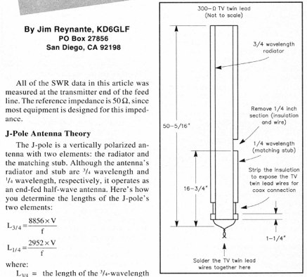 An Easy Dual-Band VHF/UHF vertical Antenna made with a TV twin lead and coax cable
 -
 Build a portable VHF yagi antenna for 2 meters. All you need is two rabbit ear antennas from Radio Shack, two CATV baluns, four feet of 3/4 CPVC pipe with one tee.
 -
 Constructing a Lindenblad antenna for 137MHz NOAA satellite reception involves specific design considerations for optimal performance. The resource details the use of 4mm galvanised steel fencing wire, 300-ohm television ribbon cable, and wood/plastic components for the antenna structure. Key dimensions for a 137.58MHz-resonant antenna are provided, derived from the ARRL Satellite Handbook, specifying s, l, w, and d as 42, 926, 893, and 654mm respectively. The antenna is designed for Right Hand Circularly Polarised (RHCP) signals, requiring the four folded dipole elements to be tilted clockwise by 30 degrees. A significant aspect covered is impedance matching between the antenna's 75-ohm impedance and a typical 50-ohm receiver input. A twelfth-wave matching transformer, constructed from 117mm sections of 50-ohm RG-58 and 75-ohm RG-59 coax with a 0.66 velocity factor, is described. The article also addresses coaxial cable and connector selection, recommending 75-ohm Type-N connectors for RG-6 cable in professional setups and F56/F59 connectors for general use, while strongly advising against PL-259/SO-259 connectors for VHF. Strategies for mitigating Radio Frequency Interference (RFI) are discussed, including antenna placement to shield from local TV transmitters and the use of commercial or DIY band-pass filters, such as cavity resonators or helical notch filters, along with ferrite chokes on coaxial cables. Antenna orientation is explored, noting the Lindenblad's 'cone of silence' directly overhead and its maximized sensitivity towards the horizon. An experimental vertical tilt of 90 degrees is presented as a method to improve overhead reception and reduce interference from strong horizontal signals, particularly relevant in high RFI environments like the Siding Spring Observatory site.
 -
 VHF UHF diplexer by G8MNY
 -
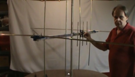
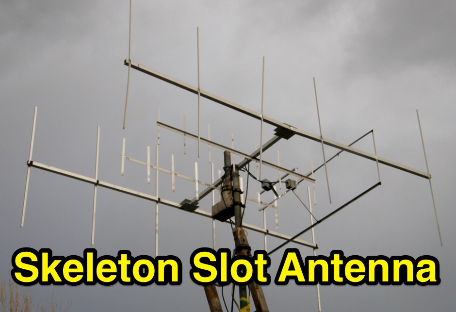 The skeleton slot antenna design was developed in the UK for TV use soon after WW2. This document describe and adapted version for the 2 meter band
 -
 This project details the construction of a **full-sized 40-meter vertical antenna**, born from a renewed interest in 7 MHz operation and a desire for improved effectiveness over simple dipoles. The author, K5DKZ, initially focused on VHF experimentation, which provided an inventory of aluminum tubing and fiberglass spreaders for this endeavor. Before this vertical, K5DKZ utilized an 80/40 meter inverted-vee trap dipole and a 40-meter broadband dipole, but now primarily uses a pair of full-sized, phased, quarter-wave verticals spaced 35 feet apart for serious 40-meter work. The construction involves a base-heavy design for stability, using a 44.5-inch section of 1-1/4 inch steel TV mast driven into 1-3/8 inch aluminum tubing, insulated by a 105-inch section of Schedule 40 PVC pipe. The assembly reaches 31 feet, close to the 32 feet required for a quarter-wavelength on 40 meters, with fine-tuning achieved by winding wire onto a fiberglass spreader. The design is explicitly presented as a foundation for a two-element 40-meter Yagi beam, outlining modifications like substituting aluminum for steel in the base and using an inductive hairpin match for the driven element. The article also discusses tuning considerations for a large 40-meter beam, noting the 100 to 200 kHz upward frequency shift when raised, and suggesting methods for installation on a tower. The author emphasizes the cost-effectiveness and good performance of the monopole approach, especially when multiple verticals are needed.
 -
 The information in this article has come from many amateur sources, the most notable was from WA6TEY (sk 1985) Ray Frost, who was a pioneer of VHF Quad designs and one of the best Southern California Transmitter Hunters. Ray built hundreds two meter quads in single and paired configurations as well as his famous mobile radio direction finding quad.
 -
 6m/2m/70cm Yagi Antenna Built from Old TV Antenna This turned out to be a great little antenna. It works the 6 meter, 2 meter and 70 centimeter bands. You can use one common feedpoint or two seperate feedpoints depending on how you would like to connect this antenna to your transceiver.
 -
 The article, "Using 75 Ohm CATV Coaxial Cable," details methods for employing readily available 75-ohm CATV hardline in standard 50-ohm amateur radio setups. It addresses the inherent impedance mismatch and practical considerations, such as connector compatibility, for hams seeking cost-effective, low-loss feedline solutions. The resource specifically contrasts common 50-ohm cables like RG-8, RG213, and _LMR-400_ with 75-ohm hardline, highlighting the latter's lower loss characteristics, particularly at VHF and UHF frequencies. It explores two primary approaches to manage the impedance difference: direct connection with an acceptable SWR compromise and precise impedance transformation. The direct connection method acknowledges that a perfect 1:1 SWR is not always critical, especially when using low-loss coax. For impedance transformation, the article explains the use of half-wavelength sections of coax to reflect the antenna's 50-ohm impedance back to the transmitter, noting its single-frequency effectiveness. It also briefly mentions transformer designs using toroid cores and a technique involving two 1/12 wavelength sections of feedline for broader bandwidth. The content further clarifies the concept of _velocity factor_ for calculating electrical versus physical cable lengths, providing a generic formula for precise length determination. It notes that while half-wave matching is practical for 10 meters and above, it can result in excessively long runs for lower bands like 160 meters, potentially adding **250 feet** of cable. The article also mentions achieving a usable bandwidth of 28.000 MHz up to at least **28.8 MHz** on 10 meters with specific transformation techniques.
 -
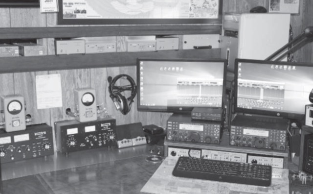 Building an amateur station for competitive radiosport involves a number of critical steps, regardless of the band or bands you focus on. These include, but are certainly not limited to: Station layout, Equipment interconnection and switching, Inter-station interference, Antenna selection. Radio interface with the logging program, CW and voice keyer integration, Rotator control
 -
 Amateur Television (ATV) operations involve transmitting and receiving live or recorded video and audio signals over amateur radio frequencies. Unlike narrow-band modes, ATV utilizes a wider bandwidth to convey video information, often requiring specialized transceivers, antennas, and signal processing equipment. This mode allows hams to share visual content, demonstrate projects, or conduct video conferences, typically on VHF, UHF, and microwave bands due to the bandwidth requirements. The SwissATV resource focuses on the technical aspects and community engagement surrounding ATV within Switzerland. It covers topics relevant to setting up ATV stations, understanding signal propagation at higher frequencies, and participating in local ATV activities. The site serves as a central point for Swiss ATV operators to exchange knowledge and coordinate transmissions, fostering the growth of this specialized amateur radio mode.
 -
 High Speed Multimedia (HSMM) radio, as introduced by John Champa, K8OCL, represents a significant advancement in amateur radio's digital capabilities, moving beyond traditional keyboard modes like packet radio. This initiative, driven by ARRL's Technology Task Force, focuses on developing high-speed digital radio networks capable of up to 20 megabits per second. HSMM primarily facilitates digital voice (DV) and digital video (ADV), enabling real-time video transmission from emergency scenes to an EOC without expensive ATV gear, often requiring only a laptop, a PCMCIA card, a digital camera, and a small antenna. The working group's initial efforts concentrate on cultivating microwave skills within the amateur community to build and support portable and fixed high-speed radio-based local networking, or **RLANs**. These networks prove invaluable for RACES and ARES organizations, as well as homeland security and other emergency communications. Field Day exercises and simulated emergency tests (SETs) are encouraged to hone skills in rapid site surveys and deploying broadband HSMM microwave radio networks, with examples like linking Field Day logging stations or antenna test results at the Midwest VHF-UHF Society Picnic 2003. Getting started with HSMM often involves adapting off-the-shelf **IEEE 802.11** (WiFi) equipment to comply with amateur radio regulations, typically operating in the 2.4 GHz ISM bands. While consumer WiFi gear has range limitations under Part 15 rules, proper setup under amateur regulations can extend coverage significantly, with test networks like the Hinternet achieving 5-15 mile ranges at 54 M bit/s using small mast-mounted dish antennas. Careful selection of equipment with external antenna ports, high transmit power, and low receive sensitivity is crucial, along with using low-loss coaxial cable like LMR-400 for optimal performance at these frequencies.