Search results
Query: low band vertical antenn
Links: 68 | Categories: 0
-
 The W5GI Mystery Antenna is a versatile multi-band wire antenna designed for amateur radio operators. It covers frequencies from 80 meters to 6 meters, making it suitable for a wide range of operating conditions. The antenna features a low feed point impedance, allowing for easy matching with most radios, whether or not an antenna tuner is used. Its construction is straightforward, requiring only two vertical supports approximately 130 feet apart, making it ideal for hams without towers. Users have reported excellent performance, particularly on the 20-meter band, where it outperforms similar designs like the G5RV. This antenna is unique in its design, incorporating three half waves in-phase on 20 meters, resulting in a six-lobe radiation pattern. Despite its effective performance, the antenna is challenging to model, which adds to its mystique. The W5GI Mystery Antenna has gained popularity among amateur radio enthusiasts worldwide, with many users praising its ease of construction and effectiveness. Whether you're a beginner or an experienced operator, this antenna offers a fun and rewarding project that can enhance your HF capabilities.
 -
 Details the construction of a **multiband vertical** antenna, specifically designed for stealth operation in a rented property, covering 80m, 60m, 40m, and 30m. The author, N3OX, leverages a 12m Spiderbeam telescoping fiberglass pole as the primary support, noting its sturdiness compared to typical fishing rods while remaining light enough for quick deployment and takedown. The radiating element is a 14 gauge Flex-Weave wire, attached to the pole's top with a rubber grommet, and fed by 27 bare 18 gauge radials spread across a 40-foot square backyard. N3OX describes the impedance matching solution, opting for custom-built L-networks over a remote tuner to enable fast bandswitching. Using an MFJ-259B and EZNEC modeling, base impedances were measured and component values calculated with G4FGQ's L_TUNER and SOLNOID_3 programs. The 80m coil is wound on a 3.5-inch PVC form, while the 30m, 40m, and 60m coils are air-wound, self-supporting #10 wire. Variable capacitors are incorporated for 40m and 30m shunt elements, with the 60m impedance matched by a series inductor. The project includes a **servo-controlled** homebrew band switch, utilizing a two-pole 12-position ceramic wafer switch for remote operation, addressing the limited 80m bandwidth. The entire matching network is housed in a weather-resistant shelter constructed from lumber and aluminum flashing. N3OX reports good DX results at 100W, estimating the total cost between $150 and $250, depending on existing parts.
 -
 The 144-430 portable j-pole antenna is designed for amateur radio operators seeking a lightweight and efficient solution for VHF and UHF communications. This antenna is particularly useful for portable operations, allowing hams to set up quickly in various locations while maintaining excellent performance. Constructed from readily available materials, it can be easily homebrewed, making it an ideal project for both beginners and experienced operators alike. The j-pole design offers a simple yet effective configuration that provides a good match across the 144 MHz and 430 MHz bands. Its vertical polarization and omnidirectional radiation pattern make it suitable for local communications and simplex operations. This antenna can be deployed in various environments, whether in the field or at home, and is well-suited for mobile applications. With proper construction techniques, operators can achieve optimal performance, enhancing their ability to make contacts during contests or casual QSOs.
 -
 The page describes a Double-L antenna for 80 and 160 meters bands, designed by Don Toman, K2KQ, with a simple, effective, and ground system-free design. The antenna is a center-fed half-wave vertical with horizontal top and bottom sections, providing good performance without the need for an elaborate ground system.
 -
 Details the construction of a J-vertical antenna specifically for the 10-meter band, offering a practical alternative to a _Slim Jim_ design for 28 MHz. The resource outlines the use of aluminum tubing for the half-wave vertical section and coaxial cable for the quarter-wave matching section, providing specific calculations for element lengths based on frequency and coaxial cable velocity factor. It contrasts the performance of the J-vertical with center-fed dipoles and end-fed verticals, noting superior results in previous comparisons. The article further presents a more recent iteration of the J-vertical, constructed using a fiberglass pole and insulated wire, with updated dimensions for 28.8 MHz. It includes practical advice on weatherproofing connections and securing the antenna for durability against adverse conditions, referencing the survival of an original _J Vertical_ during 110 MPH winds in 1987. The SWR performance is reported as 1.1:1 at 28.6 MHz, maintaining below 1.5:1 across 28.3 to 29 MHz.
 -
 The boomless quad antenna is a unique design that offers versatility for amateur radio operators. This antenna consists of two half-wave dipoles arranged in a square or circular shape, allowing for both vertical and horizontal polarization depending on the feed point. The design facilitates easy installation and rotation, making it suitable for various operating conditions. The construction utilizes strong materials, such as bamboo, and incorporates waterproofing techniques to enhance durability. This project outlines the necessary dimensions and materials, including copper wire and insulators, to successfully build the antenna. It emphasizes the importance of tuning each radiator element for optimal performance. The boomless quad is particularly effective across multiple HF bands, including 14 MHz, 21 MHz, and 28 MHz. By following the detailed instructions, operators can achieve a reliable and efficient antenna setup that enhances their DXing and contesting capabilities.
 -
 Simple wire antenna cheap to make, using readily available materials, Low angle radiation, with rejection of high angle signals Wide bandwidth, with resonance at the 80M DX window (3.790-3.800 MHz); and Maximum height is 40 feet
 -
 The RXO Unitenna, a vertical wideband antenna, offers operation across the 7-21 MHz spectrum, covering the 40, 30, 20, 17, and 15-meter amateur bands. This design focuses on achieving a low SWR across a broad frequency range, making it suitable for general HF operation without requiring an external antenna tuner for minor SWR variations. The antenna utilizes a unique loading coil and matching network to maintain efficient radiation characteristics across its operational bandwidth. Construction details within the PDF document include specific dimensions for the radiating element and the counterpoise system, which is critical for vertical antenna performance. The design incorporates readily available materials, simplifying the build process for radio amateurs. Performance graphs illustrate the SWR characteristics across the 7 MHz to 21 MHz range, demonstrating the antenna's wideband capabilities. The document also provides guidance on feedline connection and grounding considerations for optimal field deployment. This vertical antenna configuration is particularly useful for hams with limited space, offering a compact footprint compared to horizontal wire antennas.
 -
 This Vertical antenna design by David Reid for lower bands focuses on achieving effective DX communication by optimizing the antenna low-angle radiation for long-distance contacts. The design incorporates techniques like linear loading and capacity hats to reduce the antenna's height while maintaining performance, especially on 40m and 80m bands. Building a solid ground plane and using quality materials ensure efficiency and durability. Although vertical antennas can be complex to build, this project simplifies the process, making it accessible for ham operators seeking strong, reliable signals.
 -
 Examines the operational differences between **quad** and **Yagi** antenna designs, focusing on their respective performance characteristics for amateur radio applications. The document highlights key metrics such as forward gain, front-to-back ratio, and bandwidth, which are crucial for effective DXing and contesting. It discusses how element configuration, boom length, and material choices impact the efficiency and radiation patterns of each antenna type across various HF bands. Practical considerations for antenna builders are addressed, including structural integrity, wind loading, and overall weight, particularly when using fiberglass spreaders for quads. The resource also covers precipitation static reduction in quads due to their closed-loop design and their ability to operate efficiently at lower elevations compared to Yagis. It provides insights into dual-polarization feed systems for quads, offering independent vertical and horizontal feed points for enhanced operational flexibility.
 -
 a simple, low-cost, trapless short vertical antenna which amazingly works on three HF bands (20, 15 and 10 meters)
 -
 Multi Band Quad,Cushcraft R5, R7, R7000, repair and maintenance, Remote Antenna Switching, Hexagonal Beam, Automatic Band Decoder, Low Band Verticals, Crank-up Tiltover Tower etc
 -
 The Flower Pot Antenna project details a portable dual-band antenna primarily operating on 10 meters, with secondary resonance near the 30-meter band. Construction involves winding RG58 coaxial cable uniformly around a large plastic flower pot, approximately 70cm high with a 60cm top diameter. The design eliminates the need for radials, contributing to its compact and lightweight nature. Key construction steps include soldering the inner conductor to the shield at one end of the wound cable and connecting the wound cable's shield to the rig cable's inner conductor at the base. An LC network, comprising a variable capacitor (0-200pF) and an inductor (10 coils, 5cm diameter, 2mm wire), is inserted between the wound cable's inner conductor and the rig cable's shield. Tuning is performed with an antenna analyzer, adjusting cable length and the variable capacitor for optimal impedance on 10 meters. The antenna performs effectively when installed horizontally.
 -
 Demonstrates the construction and on-air performance of the _NB6Zep_ antenna, a modified 20-meter Extended Double Zepp design optimized for multi-band operation from 40 through 10 meters. The resource covers basic design principles, including dimensions of 66 feet horizontal and 5 feet vertical elements, and specifies open ladder line or TV twin lead for the transmission line. It details material selection for low-cost wire antenna construction, such as 18 AWG wire for the legs and ceramic or plastic insulators, along with practical tips for soldering connections and insulating against moisture. The author, NB6Z, shares insights from extensive _EZNEC_ modeling to optimize the antenna's total length for a 40-meter half-wave dipole footprint and feed line length for direct tuner connection. The article presents field results, including successful _PSK31_ contacts from Oregon to the East Coast on 40 and 30 meters with 50 watts, even at a low height of 6 feet. It provides detailed performance characteristics for each band, noting the _NB6Zep_'s highest gain (over 3 dB) and sharp, medium-angle lobes on 20 meters, which yielded strong DX reports to locations like Korea, Japan, and Argentina. For 17 and 15 meters, it describes a butterfly-like pattern with broad lobes, while 12 and 10 meters exhibit narrow, directional lobes in an "X" configuration. The author also shares personal experiences operating successfully for over a decade in an antenna-restricted environment using the NB6Zep and other stealth wire antennas.
 -
 This multiband wire antenna it is an off centre fed dipole, with 10 feet of vertical radiator, needs no tuner on 40m, 20m and 10m and works fine on all bands above 40m with a tuner, and even below 40m on 60m, and 80m.
 -
 This article describes the construction of a Moxon rectangle antenna for the 70MHz (4-meter) amateur radio band. This compact two-element beam design features folded element ends, reducing its width to approximately 75% of a half-wavelength. The antenna was built using enamelled copper wire stretched over a lightweight fiberglass kite spar frame, with a direct coaxial cable feed connection. Initial testing showed a VSWR of around 1.3 with distinct nulls at 90 degrees when horizontally mounted. The author later tested vertical polarization and suggested that the antenna's compact size might allow for indoor loft installation.
 -
 The Petlowany Three-Band Burner is a simple, low-cost, trapless short vertical antenna which amazingly works on three HF bands (20, 15 and 10 meters). This web page contains pictures, performance data, and enough construction details so you can homebrew your own.
 -
 A **90-foot tall** top-loaded vertical antenna for the 160-meter band is detailed, constructed from aluminum irrigation tubing. The design incorporates four sets of four guy wires for structural stability, essential for an antenna of this physical size. This _monoband_ vertical is optimized for low-band operation, providing a robust solution for DXing and contesting on 1.8 MHz. The document includes specific construction methods for assembling the aluminum irrigation tubing sections and securing the guy wires. While a full NEC model is not explicitly provided, the physical dimensions and construction materials are sufficient for replication by experienced builders. The antenna's height and top-loading configuration are critical for achieving efficient radiation on 160 meters, particularly in minimizing ground losses.
 -
 This antenna project came out very nice. It's a rugged homebrew multi-band trap vertical antenna that works the 10, 15, and 20 meter amateur radio bands. The antenna can be mounted on the ground or on a mast. Mounted on the ground the antenna has a low take off angle for working DX. If mounted on a mast the antenna will acheive both a low angle as well as another radiation lobe that has a much higher take off angle.
 -
 Constructing an HF End-Fed Half-Wave (EFHW) vertical antenna, the resource details the winding of a monoband matching unit, inspired by _AA5TB_, designed to provide a 50 Ohm impedance match without a ground plane or antenna tuner. It specifies the use of a _T200-2_ ferrite core for the transformer, outlining the 13-turn secondary and 2-turn primary winding process with enamelled copper wire. The document also describes the integration of a coax capacitor, whose length is critical for tuning and varies by band, with specific starting lengths provided for 20m, 17m, 15m, 12m, and 10m operation. The practical application section guides the builder through tuning the antenna using an antenna analyzer, emphasizing the iterative process of spacing secondary windings and trimming the coax capacitor to achieve resonance at the desired band frequency. It highlights the antenna's low angle of radiation, beneficial for DX, and claims up to 2 S-points improvement over a _G5RV_ or similar doublet when used as an omnidirectional vertical. A comprehensive shopping list, including specific part numbers from _Rapid Electronics_, is provided, along with advice on selecting fiberglass fishing poles for support and suitable antenna wire.
 -
 A simple and low cost multiband vertical hf antenna covering 5 bands (20m-10m) from an old CB antenna
 -
 End-Fed Half-Wave Antennas (EFHWAs) are analyzed for their utility in portable QRP operations, emphasizing their simplicity, efficiency, and predictable radiation patterns compared to other portable antenna types. The discussion contrasts EFHWAs with vertical antennas, random length wires, and center-fed dipoles, highlighting the common pitfalls of each, such as ground system dependency for verticals and feedline issues for dipoles. The article details the electrical half-wavelength calculation using the formula L (Ft) = 468/F(MHz) and explains how EFHWAs can be resonant on harmonic frequencies, enabling multiband operation. Various deployment configurations are presented, including the inverted L, inverted Vee, sloping wire, and vertical setups, each with specific advantages for radiation angle and polarization. For instance, a vertical EFHWA offers a low angle of radiation suitable for DX contacts without requiring an extensive ground system. The resource also addresses the counterpoise requirements, suggesting a quarter-wavelength wire or connection to a metallic structure for decoupling. A schematic diagram for a simple parallel-tuned circuit tuner, based on the _Rainbow Bridge/Tuner_ design, is provided, detailing component values for 30 and 40 meters, including a 6 microhenry toroidal inductor and a 20-100 picofarad mica compression capacitor. The tuner's adjustment process for SWR matching is also outlined.
 -
 5 Band 1/4 wave Telescopic Antenna. The 20m to 10m, antenna is simple and cheap to make, and has a performance that matches commercial antennas but at cost considerably lower. The design was purposely based on a telescoping fibre glass fishing rod as this allows it to be easily stowed away in the car.
 -
 A quarter-wave vertical antenna design for HF operation offers a practical solution for radio amateurs seeking a compact and efficient multi-band radiator. This project details the construction of a 5-band HF vertical, drawing inspiration from established commercial products such as the _DX COMMANDER_ and the MV6. The design emphasizes ease of assembly and disassembly, making it suitable for portable operations or installations with limited space. The article provides insights into various construction methods and offers practical tips for building a robust yet lightweight antenna. It highlights the benefits of a vertical configuration for DX contacts, particularly on the lower HF bands, and discusses real-world performance observations. The antenna is designed to cover multiple HF bands, providing versatility for various operating scenarios. Operators can achieve significant DX results with this type of antenna, often comparable to more complex arrays, especially when deployed with an effective ground system. The project aims to empower hams to build a capable antenna without significant financial outlay.
 -
 The page describes the construction of a simple omnidirectional, vertically-polarised dipole antenna for two metres using coaxial cable. It can be used indoors or outdoors, with no extravagant gain claims. The project is low-cost and can be completed in about 20 minutes.
 -
 A 90-foot vertical antenna constructed from **aluminum irrigation tubing** is detailed, focusing on its innovative raising and lowering mechanism. The resource describes a **45-foot ginpole** system, allowing a single operator to erect or lower the antenna in minutes. It covers the mechanical design, including the pivot base, insulated joints for the tubing sections, and guy wire attachment points. The antenna consists of two 30-foot sections of 4-inch tubing and one 30-foot section of 2-inch tubing, stacked with the smaller diameter at the top. The electrical design incorporates PVC "condulet" boxes at the 30-foot and 60-foot points, housing relays to change the effective height for multi-band operation on 160, 80, 40, and 30 meters. Ferrite rod inductive chokes are used for DC control and to tune out gap capacitance. The antenna is fed with 1000 feet of open wire line, connected to a matching transformer comprising stacked toroids and a coaxial/toroidal balun. Grounding is achieved with a 3x3 foot grid of 16-gauge tinned copper wires with soldered crossovers.
 -
 This vertical antenna consist of a 18 meters telescopic pole and allow operations from 160 to 30 meters band, project by Daniel Zimmerman N3OX
 -
 Presents a construction project for a linear-loaded 40-meter rotatable dipole, detailing the design evolution from mid-element coils to 300-ohm twinlead loading. It covers material selection, including repurposed fishing poles and EMT conduit, and outlines the assembly process for the antenna elements and mounting plate. The resource provides specific measurements for element lengths and linear loading sections, along with SWR plots demonstrating the antenna's resonance at 7.035 MHz with a 1.1:1 SWR, and bandwidth up to 7.120 MHz below 2:1 SWR. The article documents the antenna's performance during various RTTY and CW contests, including the SARTG RTTY and SCC RTTY contests in August 2006, and the ARRL DX CW and CQWW WPX RTTY contests in February 2007. It reports successful operation at 500-1000W, noting improved performance after replacing a faulty coax cable. Specific DX contacts from British Columbia, including stations in Europe and South Africa, are listed, illustrating the antenna's capability despite its shortened length and relatively low height of 55 feet. The content highlights practical considerations such as weatherproofing the connections and supporting the fiberglass elements to prevent sagging. It also includes a brief comparison to an inverted-V at similar height and a ground-mounted vertical, noting the rotatable dipole's quieter reception. The author shares insights into the iterative design process and tuning adjustments made to achieve optimal resonance.
 -
 GW4ALG's _136 kHz Pages_ document the evolution of vertical antennas for the 2200m band, starting with a prototype mounted on a house wall. This initial design, despite achieving the first **395 km** GM-GW QSO, suffered from significant insulation breakdown, high RF losses due to proximity to the house, and difficult tuning adjustments. The author details the challenges of maintaining resonance and matching with a variometer in the loft, noting that adding three earth spikes offered no measurable improvement over a simple water tap connection. The subsequent experimental 12m vertical, relocated away from the house, significantly reduced dielectric losses and proved far more effective. This antenna enabled GW4ALG to set a world DX record on 136 kHz with a **1916 km** QSO to OH1TN, and an intra-UK record of **703 km** to GM3YXM/P. The resource further explores the use of helium-filled balloons to extend the vertical radiator, achieving heights up to 27m, typically 20m, for enhanced low-band performance. Practical advice on balloon types, inflation, and critical insulation between the wire and balloon is provided, emphasizing safety and avoiding arcing.
 -
 The G5RV multiband HF antenna, designed by Louis Varney (G5RV) in 1946, is a popular compromise antenna offering good overall performance on most HF bands when paired with an external antenna tuner. The basic full-size G5RV measures 102 feet across the top for 80 through 10 meter operation and is fed at the center via a 34-foot low-loss feed-stub. This interaction between the radiating section and the feed-stub facilitates matching across 80-10 meters with a standard tuner, often eliminating the need for ladder line directly to the shack. The antenna's design center frequency is 14.150 MHz, configured as a 3/2-wave dipole on 20 meters, with its 102-foot length derived from long-wire antenna formulas. Construction details emphasize the matching section, which can be open wire, ladder line (window-type), or TV twin lead. Each type has a specific velocity factor (VF) affecting its physical length for an electrical half-wave on 14 MHz; for instance, open wire requires 33.7 feet (VF 0.97), ladder line 31.3 feet (VF 0.90), and TV twin lead 28.5 feet (VF 0.82). The article provides formulas for calculating these lengths and discusses the antenna's behavior on individual bands, from 3.5 MHz where it acts as a shortened dipole, to 28 MHz where it functions as two three-half-wave long-wire antennas fed in-phase. Practical construction notes include recommendations for vertical descent of the matching section, sealing the coax junction, providing strain relief, and winding a coaxial choke coil to mitigate common mode current. The resource also presents dimensions for double-size (204 ft) and half-size (51 ft) G5RV versions, along with their corresponding matching section lengths for various line types, making it a versatile reference for hams considering this classic wire antenna.
 -
 The NCDXF/IARU International Beacon Project operates a worldwide network of 18 high-frequency radio beacons, continuously transmitting on 14.100, 18.110, 21.150, 24.930, and 28.200 MHz. These beacons, initially launched in 1979 with a single station and expanded to the current 18-beacon system in 1995, provide reliable signals for both amateur and commercial users to assess current **ionospheric propagation** conditions. The system's design, construction, and operation are managed by volunteers, covering hardware and shipping costs. The resource details the evolution of the beacon network, including the transition from Kenwood TS-50s transmitters to Icom IC-7200 radios with a new controller design implemented in 2015. It explains how listening for these 100-watt signals, transmitted to vertical antennas, allows operators to determine band openings and optimal propagation paths globally. The content also references three QST articles providing historical context and technical specifics of the beacon project. Practical information includes methods for identifying transmitting beacons via a schedule or specialized software like FAROS and Skimmer, which integrates with the **Reverse Beacon Network** for automated monitoring.
 -
 A simple and awesome wire monoband antenna, very usefull for portable and dxpeditions usage, consist of two elements, a driver and the reflector. This endfed halfwave gives a very low take off angle and is very suited for chasing DX.
 -
 The X80 multi-band HF vertical antenna, a commercial iteration of the Rybakov design, exhibits a physical length of 5.5 meters, or approximately 18 feet, and is constructed from aluminum tubing. It operates as a non-resonant vertical, requiring an external antenna tuner for impedance matching across its intended operating frequencies. The antenna's design incorporates a 1:4 UNUN at its base, facilitating a nominal 50-ohm feed point impedance for the coaxial cable. Performance observations indicate effective operation on 40 meters, 20 meters, 15 meters, and 10 meters, with reduced efficiency on 80 meters and 160 meters due to its relatively short electrical length for these lower bands. Comparative analysis with a G5RV dipole and a half-wave end-fed antenna reveals the X80 offers a lower take-off angle, beneficial for DX contacts, particularly on the higher HF bands. Field tests conducted with an Icom IC-706MKIIG transceiver and an LDG AT-100ProII autotuner demonstrate the X80's ability to achieve acceptable SWR across 80m through 10m. The antenna's compact footprint and ease of deployment make it suitable for restricted spaces or portable operations, though its performance on 80 meters is noted as a compromise compared to full-size resonant antennas.
 -
 A vertical antenna for Six Meters band
 -
 Demonstrates the operational status and reception reports for the SK6RUD/SA6RR QRPP beacons, which transmit on 478.9 kHz, 1995 kHz, 10.131 MHz, and 40.673 MHz. These beacons utilize extremely low power, with the 630-meter beacon operating at approximately 0.1 watt ERP into an L-antenna, showcasing the potential for long-distance contacts under favorable propagation conditions. The site details the specific frequencies and antenna types employed, such as a vertical at 500 kHz and a 1/4 vertical for higher bands. The resource compiles over 10,530 reception reports from amateur radio operators worldwide, logging details such as date, time, band, RST signal report, locator, distance, and receiver setup. Notable long-distance reports include a 500 kHz reception by AA1A-Dave from 5832 km in 2008 and a 10.133 MHz reception by ZL2FT-Jason from 17680 km in 2010, illustrating the global reach of these low-power transmissions. Each log entry provides specific equipment used by the reporting station, including transceivers like the Yaesu FT817, ICOM IC-7300, and various antenna configurations such as coaxial mag loops, inverted Ls, and end-fed wires. The primary objective of the SK6RUD beacons is to challenge conventional notions of power requirements for effective two-way communication, proving that contacts over significant distances are achievable with minimal output. The site also includes a submission form for new reception reports, fostering community engagement and continuous data collection on propagation phenomena across different bands. The detailed logs offer practical insights into real-world propagation characteristics and the efficacy of QRPP operations.
 -
 Hi-Z Antennas offers specialized high-impedance receiving systems, primarily focusing on phased vertical arrays for HF reception. Their product line includes preamplifiers designed for shortened vertical antennas, featuring optimized 15dB gain and array-matched characteristics. These components are engineered to enhance weak signal reception and improve signal-to-noise ratio across the HF spectrum. The company provides controllers for managing multiple vertical elements in a phased array configuration, enabling directional reception patterns. These systems are particularly effective for mitigating local noise and interference, a common challenge in urban and suburban operating environments. Specific offerings include solutions for 160-meter and 80-meter bands, addressing the unique requirements of low-band DXing. Technical details often reference components like the 2N3866 transistor in preamp designs and discuss concepts such as out-of-band attenuation. The focus remains on optimizing receiving antenna performance through impedance matching and active amplification, rather than transmit capabilities.
 -
 A 200 kHz bandwidth digital transmission system for image transfer in the Amateur Service is under development, specifically targeting VHF allocations. John B. Stephensen, KD6OZH, leads this project under an FCC Special Temporary Authority (STA) valid until September 10, 2006, authorizing emissions up to 200 kHz bandwidth in the 50.3-50.8 MHz segment. Current regulations typically limit bandwidths to 20 kHz on VHF amateur bands, making this STA crucial for testing wideband digital modes. The modem, a modified **OFDM** (Orthogonal Frequency Division Multiplexed) unit, was initially tested on the 70-cm band. It splits a high-rate data stream into multiple low-rate subcarriers to mitigate multipath echoes. The system uses a DCP-1 card with a Xilinx XC3S400 FPGA and Oki Semiconductor ML67Q5003 microcontroller. The transmitter, located at 36d 46m 30s N, 119d 46m 22s W, generates 150 WPEP into an 8 dBi gain vertical antenna, while the mobile receiver uses a Ham-stick. Three data formats for 50, 100, and 200 kHz channels are being tested, with encoded data rates of 96, 192, and 384 kbps. Verilog code for the VHF OFDM modem is 95% simulated, with modifications from the UHF version including increased filter coefficient precision and a change from Ungerboeck **TCM** to BICM for improved performance over fading paths. Final tests will involve one-way over-the-air measurements of bit error rates and coverage area.
 -
 The NB6Zep Antenna, an electrically shortened 80-meter end-fed wire, addresses space constraints for low-band operation by integrating two loading coils into a 37-foot wire. This design, modeled with _EZNEC_, explores configurations like the quarter-wave sloper and inverted-L, with the latter providing a more vertical radiation pattern and practical backyard deployment. The resource details specific coil construction, recommending 21 uH coils made from _BW coil stock #3026_ or similar, and outlines wire segment lengths for optimal tuning. Performance analysis indicates a radiating efficiency of approximately 27% with good ground conductivity, resulting in a signal typically 3-4 dB down compared to a full-size quarter-wave vertical. The antenna exhibits a narrow bandwidth, around 50 kHz, due to its high Q, necessitating a tuner for broader band operation. Feedpoint impedance is low, with ground resistance playing a critical role in achieving a usable SWR. The article emphasizes the importance of an effective ground rod at the feedpoint for proper operation and tuning, suggesting an antenna analyzer for precise adjustments. It confirms the antenna's suitability for DX, citing successful contacts from Oregon to the East Coast and Hawaii on a 160-meter variant, making it a viable option for urban operators seeking low-angle radiation on 80 meters.
 -
 The **Solarcon A99** vertical antenna, a half-wave over a quarter-wave variable mutual inductance design, primarily serves the 11-meter CB band but also finds use on 10 and 12 meters for amateur radio operators. Its simple construction, consisting of three fiberglass sections and a 16 AWG radiating element, makes it an accessible option for new operators or those seeking an easy-to-install base station antenna without complex mounting requirements. Despite claims of 9.9 dBi gain being widely considered exaggerated, and a manufacturer rating of 2000 watts power handling often viewed with skepticism (with 300 watts suggested as a practical limit), the A99 maintains popularity due to its low cost and ease of deployment. It typically tunes to a 1.2-1.3 SWR out of the box, requiring minimal adjustment via its two tuning rings. Its high angle of radiation allows for effective local communication even when mounted at low heights, such as 8-10 feet off the ground. However, the A99 is known for significant RF bleed-over issues, particularly when operated with higher power or mounted close to residential electronics. While its internal design is often described as cheap, the antenna exhibits remarkable durability, frequently lasting a decade or more in various weather conditions. Its affordability and straightforward setup continue to make it a go-to choice for many radio enthusiasts.
 -
 Optimizing weak signal reception on the HF bands, particularly in the presence of strong local QRM, often necessitates specialized receiving antenna systems. This resource details the _HI-Z Antennas_ product line, focusing on phased vertical arrays designed for superior noise rejection and directivity. It covers components such as the 4-Square and 8-Element array controllers, which allow for rapid switching of receive patterns, and dedicated low-noise preamplifiers to improve system sensitivity. The site also presents various bandpass filters, crucial for mitigating out-of-band interference and enhancing the dynamic range of the receiver. The HI-Z systems are engineered to provide significant front-to-back and side rejection, often yielding **20-30 dB** of attenuation to unwanted signals, which is critical for DXing and contesting. Users can achieve a notable reduction in local noise, allowing for the discernment of signals that would otherwise be buried. The array controllers facilitate quick pattern changes, enabling operators to null out interference or peak weak signals from distant stations, effectively extending the reach of their receive capabilities by improving the signal-to-noise ratio.
 -
 Operating a ham station often involves encountering radio frequency interference (RFI), RF feedback, or RF burns, which are frequently misattributed to poor equipment grounding. This resource meticulously dissects these assumptions, asserting that RF grounds on the operating desk often merely mask more significant system flaws. It identifies five primary causes for RF problems, including antenna system design flaws, proximity of the antenna to the operating position, DC power supply ground loops, equipment design defects, and poorly installed connectors or defective cables. The content emphasizes that issues like "hot cabinets" or changes in SWR when connecting a ground indicate substantial RF flowing over wiring or cabinets, a phenomenon known as common-mode current. The article provides detailed explanations of common-mode current generation, particularly from single-wire fed antennas like longwires, random wires, and OCF dipoles, which inherently present high levels of RF in the shack. It also illustrates how vertical antennas, lacking a perfect ground system, can excite feed lines with significant common-mode current. Through simulations, the author demonstrates how a dipole without a proper _balun_ can cause RF problems at the operating desk, showing current patterns and voltage distributions on feed line shields. The discussion extends to the proper application of _RF isolators_ and _ferrite beads_, clarifying their role in modifying common-mode impedance on cable shields and cautioning against their use as a band-aid for fundamental system defects. The resource advocates for correcting the actual source of RF problems, such as antenna system issues or poor connector mounting, rather than relying on internal shack grounding or isolators. It highlights that properly functioning two-conductor feed lines, like coaxial or open-wire lines, should result in minimal RF levels at the operating position, even without a desk RF ground. The author shares personal experience, noting that his stations since the late 1970s have operated without RF grounds at the desks, relying instead on proper antenna system design and feed line integrity.
 -
 The Superantennas MP-1 portable HF antenna is analyzed for its design and field performance, particularly its high-Q loading coil and 3/8-inch mounting. The review details the antenna's construction, including an 8-inch vertical section, a large-diameter loading coil tuned by a sleeve, and a 4-foot whip that disassembles into six rods for transport. Initial testing with the supplied 10-foot ribbon cable "ground plane" yielded poor SWR and RF hot conditions, indicating an inadequate ground system. Further experimentation with longer radials and resonant counterpoises for each band improved matching and eliminated RF hot issues, but introduced significant operational complexity. The author notes the difficulty in optimizing both counterpoise length and coil setting without an antenna analyzer, and the sensitivity of the MP-1 to counterpoise deployment. The review also discusses the recommendation to tune for maximum received signals rather than minimum SWR, often necessitating an external ATU due to the antenna's typical low impedance. The **MP-1**'s critical dependence on resonant counterpoises for effective operation, especially when elevated, is highlighted as a major drawback for portable use. The author ultimately sold the antenna, concluding that despite its sound technical design, its fussy nature and the need for extensive counterpoise management or an ATU detract from its portability and convenience compared to simpler, less expensive dipole solutions. The **Superantennas MP-1** is deemed a flawed portable antenna, requiring considerable effort to achieve its claimed performance.
 -
 A 102-inch vertical whip, commonly a CB antenna, forms the core of this low-profile 10-meter antenna design, optimized for the 28 MHz band. The construction details specify three 8-foot radials made from scrap wire, connected to a common point. This simple yet effective setup is designed for ease of construction and deployment, making it accessible for operators with limited space or materials. The design emphasizes using readily available components, including PVC pipe for the mast and a SO-239 connector for the feedline, ensuring a straightforward build process for a resonant quarter-wave vertical. Field results indicate that this antenna provides good performance for local and DX contacts on 10 meters, despite its compact footprint. The author, N8WRL, shares practical insights into its construction and tuning, highlighting its suitability for temporary or permanent installations where a full-sized antenna might be impractical. Comparisons to more complex designs suggest that this low-profile vertical offers a respectable signal-to-noise ratio and effective radiated power for its size, proving that simple designs can yield satisfying on-air results.
 -
 The collinear antenna, or Marconi-Franklin antenna, is an omnidirectional, high-gain antenna composed of in-phase half-wave dipoles aligned vertically. By using quarter-wave transmission line segments, it maximizes gain at a low horizon angle, outperforming a half-wave dipole. Adding segments increases gain but narrows bandwidth. A popular DIY version, the CoCo antenna, uses half-wave coaxial cable segments connected by non-radiating transmission lines. Built with stable velocity factor cables, a matching quarter-wave sleeve balun, and ferrite rings for attenuation, the antenna achieves performance comparable to commercial models.
 -
 A monoband delta loop antenna for the 7 MHz. This vertically polarized DX Antenna is a full wavelength sngle side antenna and has a total length of 42.3 meters (137,1 inch) Can be easily setup with a flag pole or fishing pole as center top mast. For optimal performance lower side should be at 2 meter above the ground. This antenna offers a low radiation angle and 1 DB Gain.
 -
 The program consists of tabbed pages for various antenna and transmission line calculation. You can compute the values for an inverted L network that will allow you to match the 50 ohm output of the radio, or you can compute the necessary length in the units of choice for a 5/8 wave vertical for 10 meter band.
 -
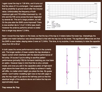 It is possible to detune the tower so that, at least on one band, the tower can be made to effectively disappear. That is, become non-resonant on the band of interest. This allows the vertically-polarized low-bands antenna to meet its potential.
 -
 Presents _Beam Quest_, the official Japanese distributor for _SteppIR_ antennas, detailing their product lineup and services. The site showcases various _SteppIR_ Yagi models, including the _Dream Beam_ series (DB42, DB36, DB18E, DB11) with configurations from two to four elements, alongside the _Big IR_ and _Small IR_ vertical antennas. It also lists accessories such as TX/RX and PC interfaces, essential for integrating these advanced antenna systems into a ham shack. Operators often seek out _SteppIR_ antennas for their dynamically adjustable element lengths, which allow for optimization across multiple bands, a significant advantage for DXing and contesting. This adaptability contrasts sharply with fixed-element Yagis, providing a distinct edge in varying band conditions. The resource provides contact information, including email and phone numbers, for inquiries and support regarding _SteppIR_ products within Japan, serving as a direct point of contact for sales and technical assistance.
 -
 This DIY vertical multi-band Windom antenna offers a practical and effective solution for amateur radio enthusiasts seeking a versatile and compact antenna for HF communications. Its simplicity of construction, multi-band capability, and favorable performance make it a valuable addition to any radio shack. The article provides detailed instructions on constructing the antenna and balun, along with diagrams and component specifications. Field tests demonstrated successful contacts with stations across Europe and North America on 14, 18, and 28 MHz. The antenna exhibited comparable performance to a W3DZZ dipole and outperformed a Cobweb antenna on 18 MHz. Low noise levels were observed, effectively suppressing background noise.
 -
 The ZS1J/B beacon operates on 28.2025 MHz with 5 Watts output to a half-wave, end-fed vertical antenna, initially installed in 1977 as ZS5VHF near Durban. The 10-meter transmitter is a modified 23-channel CB radio, and the identification keyer uses a diode matrix unit with TTL ICs from the same era. After relocation to Plettenberg Bay in 1993, the beacon has been in continuous service, with additional QRP transmitters later installed for other bands. In 1994, a single-transistor, 80-meter, 0.5-watt QRP transmitter with a half-wave dipole was added on 3586 kHz, followed by a 160-meter, 0.5-watt unit on 1817 kHz. A 30-meter, 0.5-watt transmitter was installed in 1996, operating on 10.124 MHz. In 2002, a 40-meter QRRP beacon on 7029 kHz, with an output of 100 microwatts, achieved DX reports up to 1100 km from ZS6UT in Pretoria. Best DX reports for the 80m and 160m beacons came from 9J2BO.