Search results
Query: wi fi beam antenna
Links: 60 | Categories: 1
Categories
-
 Details the construction of a **multiband vertical** antenna, specifically designed for stealth operation in a rented property, covering 80m, 60m, 40m, and 30m. The author, N3OX, leverages a 12m Spiderbeam telescoping fiberglass pole as the primary support, noting its sturdiness compared to typical fishing rods while remaining light enough for quick deployment and takedown. The radiating element is a 14 gauge Flex-Weave wire, attached to the pole's top with a rubber grommet, and fed by 27 bare 18 gauge radials spread across a 40-foot square backyard. N3OX describes the impedance matching solution, opting for custom-built L-networks over a remote tuner to enable fast bandswitching. Using an MFJ-259B and EZNEC modeling, base impedances were measured and component values calculated with G4FGQ's L_TUNER and SOLNOID_3 programs. The 80m coil is wound on a 3.5-inch PVC form, while the 30m, 40m, and 60m coils are air-wound, self-supporting #10 wire. Variable capacitors are incorporated for 40m and 30m shunt elements, with the 60m impedance matched by a series inductor. The project includes a **servo-controlled** homebrew band switch, utilizing a two-pole 12-position ceramic wafer switch for remote operation, addressing the limited 80m bandwidth. The entire matching network is housed in a weather-resistant shelter constructed from lumber and aluminum flashing. N3OX reports good DX results at 100W, estimating the total cost between $150 and $250, depending on existing parts.
 -
 High Performance Lightweight Antennas. The spider beam is a full size lightweight tribander yagi for 20/15/10m, made from fiberglass and wire. It has been specially developed as a highly efficient antenna for dx-pedition and portable use.
 -
 For radio amateurs considering homebrew antenna projects, this resource details several designs from WE6W, an experienced operator. It covers the construction and characteristics of a _160 Meter QRP Loop Antenna_ optimized for high voltage, along with standard and folded variations of the double bazooka antenna. The site also presents a unique Field Day antenna design and instructions for building a Sterba Curtain, a directional array known for its gain. Each design includes practical insights from the author's building experience. The author provides comparative data, such as the performance of a standard bazooka against a traditional dipole, offering real-world context for antenna selection. The Sterba Curtain section includes notes on its beamwidth and gain, crucial parameters for directional operation. These designs are suitable for hams looking to experiment with cost-effective, high-performance antennas for various bands and operating scenarios, from QRP on 160m to directional DXing with a Sterba Curtain, which can offer significant forward gain, often exceeding **10 dB**.
 -
 G5RV 40m Beam Antenna. Adding a 28 ft. piece of vertical wire to one end of a 102 ft. center-fed dipole turns it into a 40m beam with a very wide beamwidth
 -
 Details the construction and optimization of antenna systems for amateur radio satellite operations, focusing on practical, homebrew solutions for VHF/UHF bands. It covers building _groundplane antennas_ from salvaged materials, recycling old beam antennas into new configurations like a 2-meter crossed yagi, and constructing a 10-meter horizontal delta loop. The resource also explains antenna matching techniques, including folded dipole driven elements and quarter-wave transformers, along with the importance of accurate SWR measurements and minimizing coax loss. Demonstrates how to achieve a **1:1 SWR** by carefully trimming elements and adjusting radial angles on groundplane antennas. It provides insights into selecting appropriate coax and connectors, highlighting the benefits of Belden 9913 for low loss and the proper installation of _N-connectors_. The article also addresses RFI mitigation from computer birdies and presents a design for a silent triac antenna control circuit, offering practical solutions for common satellite station challenges.
 -
 A wire yagi antenna for 20 and 40 meters band suitable for outdoor and field day operations
 -
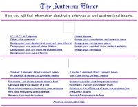 Here you will find information about wire antennas as well as directional beams.
 -
 Selecting an appropriate antenna system for shortwave broadcasting involves evaluating various types based on performance, cost, and operational parameters. This resource details the critical specifications for broadcast antennas, including average and peak power ratings, directivity, takeoff angle (TOA), horizontal beamwidth, and gain, emphasizing that a 100-kW transmitter requires an antenna rated for 150 kW average and 400 kW peak. It clarifies that low TOA signals travel thousands of kilometers, while high TOA is for local coverage, and nearly all modern shortwave broadcast antennas are horizontally polarized. The article explores specific antenna types, such as Log-Periodic Antennas (LPAs), which offer wide frequency ranges (e.g., 2-30 MHz) and directional patterns with 11 dBi gain, costing from $20K to over $100K for multi-curtain versions. Dipole arrays, also known as curtain antennas, are prevalent in international broadcasting, featuring steerable beams (±15° and ±30°) and mode-switching capabilities to alter TOA, with high/low pairs costing over $1 million. Fan dipoles are noted for omnidirectional patterns, smaller size, and lower cost for low-power applications, while rhombics, though simple, require resistive termination and incur several dB of I2R losses. Balun considerations are crucial, as most communications baluns are not rated for the higher average and peak powers of AM broadcast transmitters. Modern shortwave antennas utilize durable materials like Alumoweld wire rope for radiators and support elements, avoiding copper, fiberglass, or materials prone to stretching or deterioration. Feeder systems for high-power stations often require tapered-line baluns to convert 50-ohm unbalanced power to 300-ohm balanced for connection to the antenna.
 -
 This article describes the construction of a Moxon rectangle antenna for the 70MHz (4-meter) amateur radio band. This compact two-element beam design features folded element ends, reducing its width to approximately 75% of a half-wavelength. The antenna was built using enamelled copper wire stretched over a lightweight fiberglass kite spar frame, with a direct coaxial cable feed connection. Initial testing showed a VSWR of around 1.3 with distinct nulls at 90 degrees when horizontally mounted. The author later tested vertical polarization and suggested that the antenna's compact size might allow for indoor loft installation.
 -
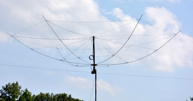
 This Multiband Cubical Quad antenna a boomless Quad design with glass-fibre arms and a single coax wire connected to a remote antenna switch. This aerial work on 8 bands and has a 60-degree beam width. Despite achieving critical technical requirements, the antenna's three-dimensional structure presents obstacles, such as installation issues on fixed towers and risk of frost damage. The spider framework is built of stainless steel, with a compact 18-inch boom and strong angle iron arms. Tait use a variety of methods to fasten element wires and suggests placing them on the outside of the spreaders for improved insulation. The use of nylon twine or parachute cord between key attachment points allows for adjustable separation between pieces.
 -
 Interesting article on mobile antennas by Cebik. . The article offers advice for setting up and operating mobile antennas for ham radio use. It emphasizes the lossy nature of mobile-in-motion antennas but encourages users to rise to the challenge. Steps include safeguarding car electronics, choosing proper cabling, and carefully selecting and mounting antennas. It highlights potential issues like roof mounting, trunk lip grounding, and side-mounting for trucks. For stationary operation, options like dipoles or beams are explored, with safety tips for masts and guying systems. Lastly, it stresses safety, suggesting stopping the vehicle to operate whenever possible
 -
 This wire-beam has one radiator-element, feeded with 450-Ohm-Wireman-twinlead and needs an antenna-tuner. For the bands 6m, 10m, 12m, 15m, 17m and 20m bended reflector-elements are used. The support is a cross of 4 fibreglass-fishing-rods
 -
 The W8JK is a famous and effective DX antenna, first built by John Kraus, W8JK, in 1937. A Beam antenna with two parallel dipoles driven with opposite phase, with a close spacing of an eighth of a wavelength.
 -
 This article describes a simple, inexpensive, dipole antenna that will rival the performance of a ten-meter beam.
 -
 Details a practical QRP wattmeter construction, leveraging a simplified SWR meter design by JA6HIC. The project focuses on a forward-only power measurement circuit, providing a functional instrument for RF power levels from milliwatts up to 5 watts. It maintains a 50-ohm input and output impedance, suitable for typical QRP transceivers and antenna systems. The resource includes the schematic for the "VSW" (Very Simple Wattmeter) and outlines a six-step alignment procedure. This calibration process involves using a known RF source up to 5W, setting full-scale deflection, and marking power increments. It also addresses minimizing frequency effects on readings with a 100pF trimmer capacitor, noting that measurement error is highest at the lower end of the scale. Construction notes mention using a piece of RG-213 coaxial cable for the inductance and coupler, with the wattmeter assembled in early 2003. The author provides an example measurement showing 0.8W into a dummy load and 1W into a 3-element beam.
 -
 The document details the optimization and construction of the _Maria Maluca_ antenna, a compact 6-band (20m-6m) directional beam. It presents a comparative analysis of shortwave antenna principles, highlighting the efficiency gains achieved by using an open feeder line and tuner as a resonant unit, contrasting this with the losses associated with traps or capacitive loads in multiband antennas. The resource specifically revisits an older South American 2-element design for 10, 15, and 20 meters, applying modern NEC-based software to develop a six-band version. Performance data is meticulously tabulated, showing impedance, free space gain, gain at 12m height, elevation angle, and front-to-back (F/B) ratio for each band from 20m through 6m. For instance, on 15m, the antenna achieves 5.1 dBd free space gain and 13.72 dB F/B ratio. The construction section provides practical guidance on element assembly using aluminum pipes and hose clamps, detailing the use of a heavy-duty glass fiber reinforced polyamide rod for electrical separation and bending strength. It also specifies the use of 450-ohm _Wireman_ line CQ 552 for the transmission line. The document includes diagrams for rod fixing, an air-wound balun, and a vertical elevation diagram for the 15m band, illustrating its DX qualification. It also discusses the antenna's suitability for portable and expedition operations, noting its compact transport dimensions (max 1.50m length, 12 lb weight) and quick assembly time (under 15 minutes). The author, Dipl.Ing. Helmut Oeller, DC6NY, is identified as a source for material kits.
 -
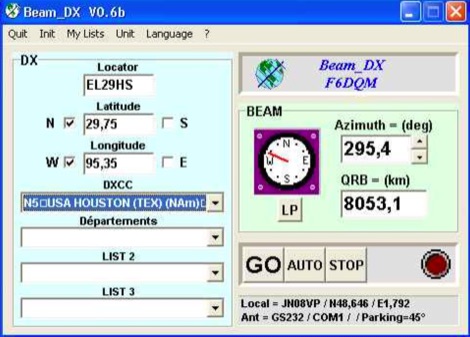 BEAM_DX is a free windows software for radioamateurs or radio listeners usage. It allows to point a directionnal antenna towards an azimuth, a locator, an international prefix or any other geographical position on earth predefined by its latitude and its longitude
 -
 JJ0DRC's HF multi-band delta loop antenna project, initially conceived during the waning peak of Cycle 23, addresses the common challenge of achieving effective DX operation from a small residential lot in Japan. Dissatisfied with a ground plane antenna's performance in SSB pile-ups, the author sought a beam-like solution without a tower, drawing inspiration from a JJ1VKL article in CQ Ham Radio Sep. 2000. The antenna, constructed in October 2000, employs two 7.2-meter fishing rods (37% carbon fiber, reinforced with cyano-acrylate glue and aluminum tape) and 1mm enameled wire, fed by an Icom AH-4 external antenna tuner. While the exact beam pattern remains unmeasured, JJ0DRC observed a significantly higher callback rate compared to dipole antennas, particularly on higher bands. The system's circumference length of 15-20m is crucial for maintaining a good beam pattern across HF bands, though performance on lower bands like 80m, 40m, and 30m becomes less directional as the length deviates from a full wavelength. Ongoing maintenance addressed degradation issues, including aluminum tape cracking and wire breakage at connection points due to strong winds (often exceeding 10-15m/s in winter). The author reinforced rod connections with IRECTOR PIPE SYSTEM components and INSU-ROCK ties, and improved wire attachment methods using Cremona rope and epoxy bond to enhance durability.
 -
 Presents a comprehensive guide for constructing a broadband Hex Beam antenna, a popular directional array for HF operation. This design offers a compact footprint and excellent gain characteristics, making it suitable for limited space installations while providing significant performance advantages over omnidirectional antennas. The resource details the specific dimensions for a five-band Hex Beam covering 20, 17, 15, 12, 10, and 6 meters, emphasizing the critical element spacing and wire lengths required for proper resonance and pattern. It outlines the construction of the center post, spreaders, and wire elements, along with the feed point assembly, ensuring proper impedance matching. The project aims for a forward gain of approximately **5.5 dBi** on most bands, with a front-to-back ratio often exceeding _20 dB_. Building this antenna requires careful measurement and assembly, but the resulting performance provides a substantial upgrade for DXing and contesting.
 -
 Hexagonal wire beams for all hf bands, technical resource, EZNEC files, tools for antenna modeling and documentation. You can also order parts to build your own antenna.
 -
 This design was adapted from an article in the ARRL Handbook and built with simplicity and duplicity in mind. This antenna is a vast improvement over a standard dipole with a forward gain of around 8db with a front to back ratio of 10db.
 -
 Demonstrates the design and construction of a compact, portable multi-band mini-delta loop antenna, specifically optimized for /P (portable) operations from remote locations like Scottish islands. The resource covers the theoretical underpinnings of half-wave loops, contrasting closed and open configurations, and then details the application of a folded dipole principle to achieve a 50-ohm match for direct coax feed. It presents empirical formulas for calculating element lengths, considering the velocity factor of common wire types, and provides a detailed example for a 20m (14.175 MHz) version. The article includes a comprehensive table of dimensions and allowances for a five-band (20m, 17m, 15m, 12m, 10m) mini-delta beam, along with construction hints for the central support and balun. It specifies a 1:1 trifilar balun wound on a ferrite rod and describes the antenna adjustment process using an _MFJ-259B Antenna Analyser_. Initial test results indicate an SWR of 1:1 at resonance and a bandwidth of approximately 240 kHz on 20m, even at a low height of five feet above ground. The distinctive utility lies in its focus on a practical, easily deployable beam antenna for portable DXing, offering a viable alternative to more complex or larger arrays.
 -
 The Vee Beam antenna project presents a versatile solution for hams, enabling operation across all eight High Frequency bands (80m to 10m) with significant gain on 20m to 10m. This easy-to-construct antenna utilizes two long wires at an angle, enhancing directional performance and minimizing ground losses. With a low visual profile, it is discreet and effective for various applications. The design allows for optimal leg lengths and included angles, ensuring robust performance while maintaining simplicity in construction and operation. The V Beam antenna is an aerial that you can use on all eight High Frequency amateur bands (80, 40, 30, 20, 17, 15, 12 and 10m) with an antenna tuner, and which gives significant gain on the five bands from 20 to 10 meters band.
 -
 Dedicated to State-of-the-Art lightweight portable radio. Sotabeams produces and sells amateur radio products dedicated to ham radio portable operations. Antennas, supports and masts, filters, wires and more accessories for amateur radio.
 -
 This project details the construction of a **full-sized 40-meter vertical antenna**, born from a renewed interest in 7 MHz operation and a desire for improved effectiveness over simple dipoles. The author, K5DKZ, initially focused on VHF experimentation, which provided an inventory of aluminum tubing and fiberglass spreaders for this endeavor. Before this vertical, K5DKZ utilized an 80/40 meter inverted-vee trap dipole and a 40-meter broadband dipole, but now primarily uses a pair of full-sized, phased, quarter-wave verticals spaced 35 feet apart for serious 40-meter work. The construction involves a base-heavy design for stability, using a 44.5-inch section of 1-1/4 inch steel TV mast driven into 1-3/8 inch aluminum tubing, insulated by a 105-inch section of Schedule 40 PVC pipe. The assembly reaches 31 feet, close to the 32 feet required for a quarter-wavelength on 40 meters, with fine-tuning achieved by winding wire onto a fiberglass spreader. The design is explicitly presented as a foundation for a two-element 40-meter Yagi beam, outlining modifications like substituting aluminum for steel in the base and using an inductive hairpin match for the driven element. The article also discusses tuning considerations for a large 40-meter beam, noting the 100 to 200 kHz upward frequency shift when raised, and suggesting methods for installation on a tower. The author emphasizes the cost-effectiveness and good performance of the monopole approach, especially when multiple verticals are needed.
 -
 A fractional bandwidth of up to 30:1 characterizes spiral antennas, making them highly effective across a very wide frequency range, often from 1 GHz to 30 GHz. The resource details two primary types: the **Log-Periodic Spiral Antenna** and the **Archimedean Spiral Antenna**, defining each with specific polar functions and illustrating their planar configurations. It explains that spiral antennas are typically circularly polarized, with a Half-Power Beamwidth (HPBW) of approximately 70-90 degrees, and a peak radiation direction perpendicular to the spiral plane. The content elaborates on critical design parameters affecting radiation, including the total length (outer radius) for lowest frequency, the flare rate ('a' constant) for optimal radiation versus capacitive behavior, the feed structure (often an infinite balun) for high-frequency operation, and the number of turns (typically 1.5 to 3 turns). It also discusses the theoretical impedance of 188 Ohms for Log-Periodic spirals, derived from Babinet's Principle, noting actual impedances are often 100-150 Ohms. The article presents a simple construction method for an Archimedean spiral, demonstrating VSWR and efficiency measurements. Measurements from a constructed spiral antenna show a VSWR that is fairly constant across the band, albeit with a mismatch loss of about 3 dB. The antenna efficiency remains around -5 dB (31.6%) across its operating range, indicating a decent wideband radiator despite opportunities for optimization.
 -
 5-element antenna, with which G0JJL has worked lots of EU crossband, and won the RSGB Christmas Cumulatives 70MHz section twice in a row.
 -
 Article describing how to homebrew a yagi antenna for 50 MHz, includes plans for a four and five elements yagi beam and details how how match impedence with a gamma match
 -
 In this PDF article Zack Lau describe how to homebrew a four element yagi beam antenna for 50 MHz band, including how to build mounting blocks and tubing clamps to hold elements.
 -
 A 5 element yagi beam antenna for ten meters band with full dimentsions, eznec file and coax match informations for 50 ohms feed line
 -
 Constructing a compact directional antenna for the 17-meter band, this resource details the build process for a Moxon rectangle, a two-element Yagi variant with folded-back elements. It covers the antenna's evolution from the _VK2ABQ beam_ and provides specific dimensions for a version built using fishing pole whips. The content includes a discussion of the antenna's radiation pattern, feedpoint impedance, and its inherent front-to-back ratio, which is often superior to a standard two-element Yagi. Practical considerations for element spacing and material choices are also addressed, alongside a visual representation of the antenna's physical layout. Performance data presented includes a comparison showing the Moxon rectangle's **2.5 dB gain** over a half-wave dipole and a front-to-back ratio of **20 dB**. The resource also touches upon the antenna's relatively wide bandwidth for a two-element beam and its suitability for portable operations due to its compact footprint. It offers insights into optimizing the design for specific operating conditions and discusses the advantages of its lower take-off angle compared to omnidirectional wire antennas, making it effective for DX contacts on the 17-meter band.
 -
 DX Maps provides a specialized map printing service, focusing on amateur radio applications such as world prefix maps and custom great circle projections. The platform allows radio operators to visualize propagation paths and DX entities relevant to their QTH and operational goals. This service supports the creation of high-quality, large-format maps tailored for shack display or operational planning. The service facilitates the generation of personalized maps, which can include specific callsign locations, beam headings, and other critical amateur radio data points. Users can specify parameters to create maps that aid in understanding global propagation conditions and optimizing antenna aiming for long-distance contacts. The UK-based operation ensures a localized service for European hams, with international shipping options available. DX Maps also offers QSL card printing, complementing its mapping services.
 -
 Presents _Beam Quest_, the official Japanese distributor for _SteppIR_ antennas, detailing their product lineup and services. The site showcases various _SteppIR_ Yagi models, including the _Dream Beam_ series (DB42, DB36, DB18E, DB11) with configurations from two to four elements, alongside the _Big IR_ and _Small IR_ vertical antennas. It also lists accessories such as TX/RX and PC interfaces, essential for integrating these advanced antenna systems into a ham shack. Operators often seek out _SteppIR_ antennas for their dynamically adjustable element lengths, which allow for optimization across multiple bands, a significant advantage for DXing and contesting. This adaptability contrasts sharply with fixed-element Yagis, providing a distinct edge in varying band conditions. The resource provides contact information, including email and phone numbers, for inquiries and support regarding _SteppIR_ products within Japan, serving as a direct point of contact for sales and technical assistance.
 -
 Designing and constructing a two-element receiving loop antenna array for HF operation involves specific considerations for achieving high directivity and noise reduction. This resource details a homebrew system comprising two 30-inch diamond-shaped loops, spaced 20 feet apart, which are fed through mast-mounted preamplifiers and passive signal combiners. The operational principle relies on adjusting phase delays between elements via precise _Belden 8241_ coaxial cable lengths, optimized for specific bands from 160m to 20m. Performance data, derived from _EZ-NEC_ modeling, illustrates consistent 90° azimuth-plane beamwidth and low take-off angles across the target bands, with _Receiving Directivity Factor_ (RDF) values comparable to a 300-foot Beverage antenna. The article presents detailed elevation and azimuth plots for 20m, 30m, 40m, 80m, and 160m, demonstrating the array's ability to provide strong response at low DX angles while also supporting _NVIS_ signals. Key components like the _DX Engineering RPA-1_ preamplifier and _DXE RSC-2_ signal combiner are discussed, alongside the importance of impedance matching to preserve antenna patterns. The construction emphasizes self-contained elements that do not require ground radials, offering a compact solution suitable for suburban environments and stealth installations, with a focus on optimizing receive performance independently from transmit antennas.
 -
 A portable operation experience with a SpiderBeam pole during a contest, testing wire antennas, like dipole and delta loops configurations on 20 40 and 80 meters band.
 -
 New generation Hex Beam Antennas. VHQ HEX Products, located in Peterborough, NH, is owned and operated by David M. Lavoie. Our products are designed to solve issues encountered in Ham radio applications and move with todays configurations in an ever changing climate
 -
 Documents S21RC's construction of an impedance transformer harness for a VHF/UHF cross yagi, utilizing 20m of _RG179_ cable. Details the creation of a DIY RF sampler with a -50dB sampling output, primarily for measuring HF radio PA section output with a Spectrum Analyzer, also applicable for _Pure Signal_ transmission. Chronicles the deployment of a 200m long beverage antenna for the _S21DX IOTA_ operation in 2022, positioned 2m above ground. Discusses the construction of a 3-element short beam for 10m to replace a previous 2-element antenna, with assistance from S21DW. Provides guidance on operating cheap _PA-70_ and _PA-100_ type Chinese SSPAs using IRF530 MOSFETs, emphasizing the necessity of a final LPF. Outlines the design and construction of a fully isolated interface for radio-to-computer connections, supporting various digital modes with isolated ground, audio transformers for IN/OUT, optical isolation for CAT/CIV, and isolated PTT/COS lines. Includes a log of software updates, such as the _HMI/TFT for NX8048K070_ and _2.1.14 Lite_ release with bug fixes for PEP hold and gradual watt decay.
 -
 This article provides a detailed guide on how to build a no holes roof mount for ham radio antennas. The author shares their design that can hold 2 masts and offers tips on installation. The mount is versatile and can handle small 144 Mhz or 432 Mhz beams, as well as small verticals. With adjustable angles and spacing, the mount can be customized to fit different roof types. Additionally, the author suggests affordable options for obtaining Dish antenna mounts. Overall, this DIY project offers a cost-effective solution for ham radio operators looking to mount antennas on their roofs.
 -
 With an eye to the final cost I have built a good 20 meter monoband Hex Beam antenna.
 -
 2 Wavelength ,2 Meter Bi-Square Beam , 5dbd gain. This antennas are very cheeap to build and their radiation pattern is similar to a figure 8 with maximum signal through the loop but they may be used as a near-omnidirectional antenna
 -
 The PAC-12 Antenna, a multi-band portable vertical, is meticulously detailed in this construction article by James Bennett, _KA5DVS_. The design emphasizes ease of homebrewing using readily available components from local hardware stores, including replaceable loading coils. It outlines the preparation of the 72-inch telescoping whip (originally from Radio Shack, with an alternate source now provided by _Pacific Antenna_), the construction of the loading coils from PVC risers, and the fabrication of the aluminum rod base sections. Specific instructions cover threading aluminum rod with a _1/4-20 threading die_ and assembling the feedpoint insulator with a BNC connector, along with recommendations for radial deployment. KA5DVS, an avid traveler and QRP enthusiast, developed the PAC-12 to address the bulkiness of random wire setups and the limitations of commercial portable antennas like the Outbacker or SuperAntennas MP1. His goal was a lightweight, packable antenna that disassembles into 12-inch sections, achieving an assembled length of approximately 8 feet. The design strategically places the loading coil away from the base for improved efficiency. The PAC-12 notably placed first in efficiency compared to a quarter-wavelength wire vertical at the HFPack antenna shootout during the Pacificon conference in October 2001, demonstrating its practical performance for field operations. Appendix C showcases various _NJQRP Club_ members' PAC-12 constructions, including a 20m beam made with multiple PAC-12 elements.
 -
 A dual band 40-80 vertical antenna on an 18m Spiderbeam Fiberglass Spiderpole, with monoband performance
 -
 The original HEXBEAM was developed by Mike Traffic, N1HXA, in the early nineties. It is true that an M over W configured yagi antenna that resembled a butterfly was earlier tried successfully. But the advanced electrical design, the characteristic nesting concept and central terminal post that enable the multi band functionality along with the basic hardware design were all developed by Mike Traffie.
 -
 The author reflects on expanding their antenna for 80m coverage during lockdown. They extend the End Fed Half Wave (EFHW) using a Spiderbeam pole and "cheating" by dog-legging across their garden. Despite challenges, they achieve coverage for multiple bands with minimal cost. Practical Wireless features EFHW antennas, including a pre-made 20m EFHW extended for 40m.
 -
 This project involves constructing a dual-band Moxon antenna, optimized for ham radio enthusiasts, with functionality on both the 10-meter and 6-meter bands. The antenna is designed to operate using a single 50-ohm feedpoint, acting as a mini-beam on 28 MHz (10 meters) and as a 2-element Yagi on 50 MHz (6 meters). Performance-wise, it offers a 4.0 dBd gain on 10 meters and 4.3 dBd on 6 meters, with impressive front-to-back ratios of 30 dB and 11 dB, respectively. Builders like Aleks (S54S) and Marcio (PY2OK) have successfully brought this design to life using the provided specifications. Aleks noted that bending the corners of the structure proved especially useful during assembly. The project comes with a detailed parts list, highlighting the use of aluminum tubes with different diameters and lengths to form essential components like the reflectors and radiators. For those looking to fine-tune the antenna, adjustments can be made by altering the length of certain parts that fit into larger tubes. The feeding system is equipped with a balun to accommodate different power levels, making the design versatile enough to handle outputs of either 300 watts or 1 kilowatt.
 -
 This is a design based on the QuickYagi 4 software by WA7RAI with some changes for practical reasons. The beam uses 6.5 metres of standard 25mm square boom, 12mm diameter elements without tapers. The actual boom length used is 6.3 metres and all parts are readily available.
 -
 Learn how to build wire Yagi antennas for your ham radio setup. Discover how smaller wire elements can offer practical and portable options for temporary operations. Explore designs like the Hex Beam, Spider Beam, and Moxon that require less mechanical complexity and can be easily rotated or supported. Find out how to construct and hang wire Yagis from ropes, trees, or masts with inverted vees or horizontal elements. Get tips on element positioning, gain, and beamwidth considerations. Follow simple construction steps using a rope boom and marking element positions for efficient assembly. Enhance your ham radio experience with versatile wire Yagi antennas.
 -
 The article describes a high-gain, compact beam antenna design for the 2-meter band (144-146 MHz). The NSH 4x4 Boomer is a 4-element antenna that is mounted on a 4-foot boom with an 8.2 dB gain, 1.2:1 SWR, and a front-to-back ratio of 18 db. It is designed for mobile operations and little area, making it perfect for field usage such as disaster management. The design employs regularly spaced parts with a straightforward gamma match for tuning, and the construction materials include a square boom and polished aluminum tubes. In local and portable tests, the antenna worked regularly, achieving contact distances of up to 15 kilometers.
 -
 The PA0FRI Unbalanced/Balanced ATU is a home-built antenna tuner designed to efficiently match a W8JK 2-element beam antenna fed with a 450-ohm twin lead. Based on PA0FRI’s S-Match design, it optimizes energy transfer while maintaining balance, reducing losses, and ensuring proper radiation. The tuner uses a roller inductor, air variable capacitors, and a T200 iron powder coil, allowing fine-tuning across 14-50 MHz. Extensive lab tests confirm minimal attenuation and precise impedance matching, making it a reliable and efficient ATU for balanced antennas.
 -
 From March 2 to March 11, 2018, a Norwegian team operated as Z2LA from Zimbabwe, focusing on 160m through 10m bands using SSB and CW modes. The operation, described as "holiday style," aimed to provide contacts for DXers worldwide seeking a rare DXCC entity. Key equipment included a SUNSDR PRO II, an Elecraft KX3, and an Icom 706 MK2G as a spare radio, supported by two Juma 1000 amplifiers for robust signal output across the bands. Antenna systems were tailored for multi-band operation, featuring an Inv L for 160m and 80m, sloping dipoles for 30m/40m, and a _Hexbeam_ from SP7IDX Technology covering 20m to 10m. For improved reception, the team deployed a SAL 30, two reversible BEV antennas from remoteqth.com, and a BOG from K1FZ, enhancing their ability to hear weak signals. QSL information directs operators to Clublog for log search and M0OXO Charles for OQRS, explicitly requesting no bureau cards. The team comprised LA7THA Rune, LA7WCA Arne, and LA9VPA Thor, successfully making numerous contacts and contributing to the DX community's pursuit of _Zimbabwe_ as a DXCC entity.