Search results
Query: am antenna to sw
Links: 253 | Categories: 4
-
 Demonstrates the construction of a **multi-band HF mobile antenna** utilizing a modified CB whip antenna base. The resource details the process of stripping a commercial CB whip, winding a new helical coil with 0.7mm insulated copper wire, and identifying tapping points for various HF bands. It emphasizes the importance of a rugged, slim design for mobile operation, discussing mechanical length, power handling (up to 200 watts), and coil diameter considerations. The article includes a graphic illustrating the antenna's operational principle, where sections of the helical coil are shorted from bottom to top to maintain efficiency and high Q. The resource presents a practical approach to achieving **band switching** without an external tuner, by manually adjusting tapping points on the coil. It provides a table with reference lengths in centimeters from the feedpoint for 7 MHz (40m) through 28.7 MHz (10m), including WARC bands. The author details mounting techniques, suggesting a Diamond bracket for secure attachment to a vehicle trunk, and stresses the critical role of proper grounding for optimal performance. The design allows for operation on 75m and 80m bands by adding a 110mm steel whip.
 -
 This resource provides comprehensive instructions for constructing a 2 element quad antenna specifically designed for the 10, 12, and 15 meter bands. The antenna features a diamond configuration, which offers improved gain compared to a square configuration. The author shares insights into the materials used, including a square-aluminum boom and bamboo poles, along with construction techniques that ensure durability and optimal performance. This project is ideal for amateur radio enthusiasts looking to create their own antennas at home. In addition to construction details, the author discusses the antenna's performance, noting its effectiveness even at a height of 8 meters. The quad antenna reportedly performs comparably to a 3 element yagi, with excellent SWR readings and strong signal reports from European stations. This project is suitable for beginners and offers a cost-effective solution for those interested in enhancing their amateur radio setup with a homemade antenna.
 -
 Details the construction of a **multiband vertical** antenna, specifically designed for stealth operation in a rented property, covering 80m, 60m, 40m, and 30m. The author, N3OX, leverages a 12m Spiderbeam telescoping fiberglass pole as the primary support, noting its sturdiness compared to typical fishing rods while remaining light enough for quick deployment and takedown. The radiating element is a 14 gauge Flex-Weave wire, attached to the pole's top with a rubber grommet, and fed by 27 bare 18 gauge radials spread across a 40-foot square backyard. N3OX describes the impedance matching solution, opting for custom-built L-networks over a remote tuner to enable fast bandswitching. Using an MFJ-259B and EZNEC modeling, base impedances were measured and component values calculated with G4FGQ's L_TUNER and SOLNOID_3 programs. The 80m coil is wound on a 3.5-inch PVC form, while the 30m, 40m, and 60m coils are air-wound, self-supporting #10 wire. Variable capacitors are incorporated for 40m and 30m shunt elements, with the 60m impedance matched by a series inductor. The project includes a **servo-controlled** homebrew band switch, utilizing a two-pole 12-position ceramic wafer switch for remote operation, addressing the limited 80m bandwidth. The entire matching network is housed in a weather-resistant shelter constructed from lumber and aluminum flashing. N3OX reports good DX results at 100W, estimating the total cost between $150 and $250, depending on existing parts.
 -
 This resource details the fundamental aspects of deploying longwire antennas, emphasizing ease of construction and installation for shortwave listening (SWL) and broadcast reception. It covers wire gauge selection, suggesting 14 to 24 AWG for general use, with heavier gauges (14-20 AWG) for permanent outdoor installations. Guidance is provided for various deployment scenarios, including indoor setups where the wire can be run around a room, temporary outdoor installations from balconies using light 18-24 AWG wire, and permanent outdoor configurations requiring higher placement and slack for tree movement. Feeding methods are discussed, recommending coaxial cable (50-75 ohms) to mitigate man-made interference, with instructions for connecting only the center conductor to the longwire. Safety precautions are highlighted, particularly avoiding contact with power lines and conductive materials, and managing static electricity buildup by unplugging the antenna after use and bleeding off charges before connection. The article also advises against using outdoor longwires during thunderstorms or snowstorms due to static and lightning risks. Optimal height considerations are presented, advocating for the highest safe placement, ideally a couple of feet above underlying structures, to maintain free air space. The text mentions a personal setup with one end at a roof peak (20 feet) and the other at a 17-foot mast, illustrating practical deployment without strict height requirements beyond safety and clearance.
 -
 Demonstrates the construction of **magnetic loop antennas**, detailing both multi-turn and single-turn designs. It covers a 30-inch diameter multi-turn loop for 80 meters, based on a February 1996 QST article, and an octagon single-turn loop made from 15mm copper tube with a 4.8-meter circumference, operating from 7 MHz to 14 MHz. The document also presents a smaller 800mm diameter loop for 14 MHz to 28 MHz, emphasizing the importance of high-voltage tuning capacitors. Covers the design and construction of custom **butterfly capacitors** and piston capacitors, including a split stator capacitor with 140 pF capacitance and a 6000 Volt rating, and a butterfly capacitor with 5-65 pF and 7200 Volt rating. It explains why butterfly capacitors are preferred over split stator types for high power applications due to lower losses and direct series connection of rotors, reducing resistive losses from wiper contacts. Material recommendations include clear PVC for plates and brass or stainless steel for non-magnetic hardware. Addresses practical considerations such as feeding the loop with a shielded 1/5 Faraday loop made from RG213 or RG8 coax, achieving VSWR 1.1 across bands, and optimizing its placement 180° from the capacitor. It also discusses mechanical joint resistance, dissimilar metal oxidation prevention using Vaseline, and a simple method for determining radiation angle with a TL-light tube. The guide includes diagrams for rotor, stator, and end plate construction.
 -
 MFJ manufacturer of ham radio antenna products, antenna tuners, antenna analyzers, morse code & CW, SWR wattmeters, antenna accessories , power supplies, audio filters, TVI filters, baluns, coax switches and more
 -
 Manufacturer of amplifiers, antenna switches antenna Tuners, wattmeters and relay buffers, amplifier accessories, antennas and tubes and parts
 -
 Base station and repeater antennas, mobile antennas, ,multi-band HF antennas , handheld transceivers, receiving and scanner antennas, power meters, swr meters, power supplies, coaxial switches
 -
 Short guide to home made antennas for shortwave reception, in pdf format
 -
 Build your mobile antenna which outperforms Hustler by 10db and ATAS-100 by 18db. From 80 to 10m. The HB9ABX mobile HF antenna, designed for 10 to 80 meters, was developed by Felix Meyer and outperforms commercial antennas like HUSTLER and YAESU ATAS-100/120 in field tests. Made from fiberglass rods and enamelled copper wire, it includes a loading coil with adjustable taps for tuning across bands. Installation requires solid grounding, and adjustments are made via whip length and coil settings. An antenna tuner ensures optimal SWR. Users must handle fiberglass with care due to health risks. This design proved highly effective in South America and Europe.
 -
 Details the construction of a J-vertical antenna specifically for the 10-meter band, offering a practical alternative to a _Slim Jim_ design for 28 MHz. The resource outlines the use of aluminum tubing for the half-wave vertical section and coaxial cable for the quarter-wave matching section, providing specific calculations for element lengths based on frequency and coaxial cable velocity factor. It contrasts the performance of the J-vertical with center-fed dipoles and end-fed verticals, noting superior results in previous comparisons. The article further presents a more recent iteration of the J-vertical, constructed using a fiberglass pole and insulated wire, with updated dimensions for 28.8 MHz. It includes practical advice on weatherproofing connections and securing the antenna for durability against adverse conditions, referencing the survival of an original _J Vertical_ during 110 MPH winds in 1987. The SWR performance is reported as 1.1:1 at 28.6 MHz, maintaining below 1.5:1 across 28.3 to 29 MHz.
 -
 QRZ.com provides a comprehensive online **callbook** service, enabling amateur radio operators to look up detailed information for over 2 million licensed stations worldwide. Each entry typically includes the licensee's name, address, QSL route, and often a personal biography with station details, antenna configurations, and operating interests. The platform integrates various features such as a **Logbook of the World (LoTW)** interface, allowing users to confirm QSOs directly, and a robust search engine for rapid call sign resolution. The resource also features dynamic content, including real-time solar-terrestrial data from N0NBH, an active online swapmeet for buying and selling amateur radio gear, and a news section with articles covering current events, contest results, and special event station announcements. Recent news items highlight topics like the 'Five Two Simplex Challenge' and the '9th HamSCI Workshop,' indicating a focus on active operating and scientific engagement within the amateur community. Furthermore, QRZ.com supports various amateur radio awards, such as the new 'USA250 Award,' encouraging participation in specific operating programs.
 -
 The Cubical Quad antenna is a popular choice among amateur radio operators due to its robust design and excellent performance characteristics. This resource provides essential scaling formulas that help determine the lengths of the antenna elements and the necessary gamma match values for various frequencies. The design is adaptable, allowing operators to optimize for gain or front-to-back ratio by adjusting the spacing between elements. The accompanying Excel files facilitate precise calculations, making it easier for both beginners and experienced hams to construct their own Cubical Quad antennas. In addition to the design formulas, the resource includes practical insights from the author, who has successfully built and utilized these antennas in various field events. The document outlines the tuning process for achieving minimum VSWR, ensuring optimal performance. With detailed illustrations and performance data, this guide serves as a comprehensive reference for anyone looking to delve into Cubical Quad antenna construction and optimization, enhancing their amateur radio experience.
 -
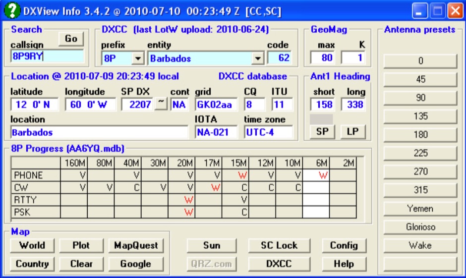 A free application that displays location information determined from a callsign, displays translations of common "QSO words and phrases" in the languages used in the callsign's DXCC entity, displays beam headings and SpotCollector DX Spots on a world map, displays country maps, and provides point-and-click control of antenna rotators from AlfaSpid, ARSWIN, Heath, Hygain, M2, Prosistel, SARTek, TIC, Trackbox, and Yaesu
 -
 Amateur radio operators often seek reliable equipment for various modes and bands, from QRP operations to high-power DXing. Historically, Ten-Tec has been a notable manufacturer in the amateur radio market, known for its range of products including HF and VHF transceivers, RF amplifiers, and antenna analyzers. Their product line also encompassed specialized items such as QRP transceivers and kits, catering to enthusiasts of low-power communication, and antenna tuners for impedance matching. The company's offerings included test equipment vital for shack setup and maintenance, like SWR meters and RF analyzers, which assist in optimizing antenna systems and ensuring efficient power transfer. Additionally, Ten-Tec provided various accessories and components, supporting both commercial products and homebrew projects. The brand was recognized for its _made in the USA_ manufacturing, appealing to operators who prioritize domestic production. While the website currently displays limited product information, it mentions upcoming items like the _MODEL 594 PHOENIX_ and the _Tune-A-Tenna_, indicating potential future product releases.
 -
 ACOM international, manufacturer of HF power amplifiers, HF Antennas, Antenna tuners, Switches and Crankup masts
 -
 The RXO Unitenna, a vertical wideband antenna, offers operation across the 7-21 MHz spectrum, covering the 40, 30, 20, 17, and 15-meter amateur bands. This design focuses on achieving a low SWR across a broad frequency range, making it suitable for general HF operation without requiring an external antenna tuner for minor SWR variations. The antenna utilizes a unique loading coil and matching network to maintain efficient radiation characteristics across its operational bandwidth. Construction details within the PDF document include specific dimensions for the radiating element and the counterpoise system, which is critical for vertical antenna performance. The design incorporates readily available materials, simplifying the build process for radio amateurs. Performance graphs illustrate the SWR characteristics across the 7 MHz to 21 MHz range, demonstrating the antenna's wideband capabilities. The document also provides guidance on feedline connection and grounding considerations for optimal field deployment. This vertical antenna configuration is particularly useful for hams with limited space, offering a compact footprint compared to horizontal wire antennas.
 -
 How can you vastly improve your Medium Wave reception? its quite simple really, all you need is 120 foot of wire, a few lengths of timber and an old tuning capacitor with which you can build the answer to every DX'ers prayers, a tuned loop antenna.
 -
 Determining the actual need for an antenna tuner often hinges on the specific antenna and feed line configuration in use. While many hams believe a tuner is always essential, its primary role is to present a 50-ohm impedance to the transceiver, not to "tune" the antenna itself. For instance, a resonant dipole fed with _coaxial cable_ at its design frequency typically requires no tuner, as the feed line impedance closely matches the radio's output. However, operating a non-resonant antenna, or using a resonant antenna on multiple bands, frequently necessitates a tuner to manage high Standing Wave Ratio (SWR) on the feed line. The article clarifies that a tuner placed at the transceiver only matches the radio to the feed line, not the antenna to the feed line. For maximum efficiency with a non-resonant antenna, an _automatic antenna tuner_ (ATU) or a remote tuner placed at the antenna feed point is often more effective, minimizing losses in the feed line. The discussion also touches on the practical implications of SWR, noting that modern transceivers often fold back power at high SWR, making a tuner a practical necessity to achieve full output power, even if the antenna itself is not perfectly matched.
 -
 Program that produces antenna radiation patterns and graphs for SWR, forward gain, and F/B ratios
 -
 The project details a DIY SWR/Wattmeter designed around an _Arduino Uno_ shield, providing capabilities to measure RF power from 2 to **200 watts** and Standing Wave Ratio (SWR) for HF amateur radio bands. This construction features a compact design, integrating the measurement circuitry directly onto a custom PCB that interfaces with the Arduino Uno microcontroller. Key components include a directional coupler for sensing forward and reflected power, precision rectifiers, and analog-to-digital conversion for processing RF signals. The Arduino firmware handles calibration, calculations, and displays the results on an integrated LCD, offering real-time feedback on antenna system performance. The design prioritizes simplicity for homebrewers. Performance specifications indicate accurate readings within the **2-200W** power range, suitable for typical QRP to medium-power HF operations. The project provides schematics and a basic overview of the software logic.
 -
 Based on HB9CV, F6ITV decribes how build a swiss quand antenna for 28 and 50 Mhz.
 -
 A well documented plan to build a magnetic loop antenna for Shortwave Listening, includes photos and diagrams.
 -
 Details the construction and optimization of antenna systems for amateur radio satellite operations, focusing on practical, homebrew solutions for VHF/UHF bands. It covers building _groundplane antennas_ from salvaged materials, recycling old beam antennas into new configurations like a 2-meter crossed yagi, and constructing a 10-meter horizontal delta loop. The resource also explains antenna matching techniques, including folded dipole driven elements and quarter-wave transformers, along with the importance of accurate SWR measurements and minimizing coax loss. Demonstrates how to achieve a **1:1 SWR** by carefully trimming elements and adjusting radial angles on groundplane antennas. It provides insights into selecting appropriate coax and connectors, highlighting the benefits of Belden 9913 for low loss and the proper installation of _N-connectors_. The article also addresses RFI mitigation from computer birdies and presents a design for a silent triac antenna control circuit, offering practical solutions for common satellite station challenges.
 -
 Presents a practical design for a **crossed-dipole turnstile antenna** specifically engineered for 2-meter Amateur Radio Direction Finding (ARDF) events. The author, WB6RDV, details a robust, omnidirectional, horizontally-polarized antenna, addressing the international ARDF rules requiring such characteristics at a height of two to three meters above ground. This contrasts with the vertical polarization often used in Southern California, highlighting the design's adherence to specific event requirements. The electrical design employs a classic crossed-dipole with a 75-ohm phasing section, resulting in a slight impedance mismatch and an SWR of approximately 1.3:1 with a 50-ohm feedline. Construction utilizes readily available and inexpensive PVC plumbing components and 1/8-inch bronze welding rod for elements. The guide provides step-by-step instructions for mechanical assembly, including drilling element holes at precise 90-degree spacing and preparing the RG-179 matching section. WB6RDV shares insights from his own build experience, discussing the use of plated brass versus aluminum spacers for element attachment and the effectiveness of crimping as an alternative to soldering. The document also covers final assembly, including the integration of ferrite beads as a choke balun and options for weatherproofing and alternative mounting configurations, emphasizing the adaptability of the design for other VHF bands through scaling.
 -
 How to build a beverage antenna. How to deploy a BOG antenna for your next SWL DX-ing activity. Give it a try and follow the orientation tips for this bi-directional antenna.
 -
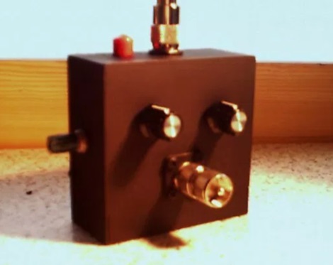
 Demonstrates the construction of a **remote antenna tuner** utilizing a standard radio-controlled (RC) servo mechanism to adjust a variable capacitor. The design focuses on enabling remote tuning for narrow-bandwidth antennas, specifically mentioning frame and packing crate antennas, from within the shack. It covers the mechanical arrangement for integrating the servo with a capacitor and provides a circuit diagram for a control unit that generates the necessary 0.5mS to 1.5mS pulse-width modulation (PWM) signals to drive the servo's 180-degree rotation. This setup was successfully tested with up to 20 watts RF power without arcing or adverse effects on the servo, though tuning was performed at 1 watt for VSWR readings. The resource highlights the use of inexpensive, readily available components, such as Futaba servos, and details critical considerations like power supply decoupling with a 47uF capacitor to prevent unintended servo movement upon power-off. The system provides a practical solution for optimizing antenna performance for specific frequencies without manual adjustment at the antenna itself.
 -
 M1IOS Wonder Whip antenna - The M1IOS Wonder Whip A 10 dollars QRP Portable Multiband Antenna for HF, VHF and UHF A variation on the Miracle Whip and Wander Wand. This antenna tuning unit will get your SWR really low on telescopic whips, mobile 3/8th antenna and long wires. A remarkable little tuner that really works!
 -
 Presents the KE4UYP linear-loaded vertical antenna design, which introduces very little loss on 80 or 160 meters, achieving an overall radiation efficiency of 80% to 85%. This design addresses common pitfalls of traditional base-fed verticals by placing the majority of the current at the top of the antenna, eliminating the heavy reliance on extensive ground radial systems. The author's initial 10-meter model, only three feet tall, yielded 5/9 signal reports to Anchorage, AK, and Europe, confirming its effectiveness. The antenna incorporates both vertically and horizontally polarized radiators, with a 1/4 wavelength horizontal counterpoise located at the feed-point, near the top, to create an almost totally omnidirectional pattern with high wave angle horizontally polarized radiation. This dual polarization ensures even illumination across all take-off angles, making it effective for both local contacts and **DXing**. The vertical element is linear loaded, adding capacitance reactance and making it longer than the horizontal element to achieve resonance and raise the feed-point impedance to 50 ohms. Fine-tuning the antenna requires careful adjustment, as tower reactance can vary. The article suggests starting with 80 feet for 80m and 170 feet for 160m for the vertical wire, then trimming for resonance. Bandwidth specifications include 300 kHz under 2:1 **SWR** on 80m and 100 kHz on 160m when suspended between trees, or 150 kHz on 80m when side-mounted on a tower.
 -
 Multi Band Quad,Cushcraft R5, R7, R7000, repair and maintenance, Remote Antenna Switching, Hexagonal Beam, Automatic Band Decoder, Low Band Verticals, Crank-up Tiltover Tower etc
 -
 Maco Manufacturing, HF Antennas, gamma matches, cable assemblies, power supply, swr meters, watt meters
 -
 Ham Station description of HB9ABX and CE3CWF, magnetic loop antenna details, Free Energy devices, Pictures from Switzerland and Chile.
 -
 Over 30 distinct shortwave (SW) receiver models are reviewed, offering insights into their performance, features, and user experiences. These evaluations, contributed by readers of the Usenet newsgroup **Rec.radio.shortwave**, cover a wide array of portable and tabletop radios, including popular units like the Grundig YB-400, Sony ICF-SW77, and various Realistic DX series models. Each review details aspects such as frequency range, tuning steps, SSB functionality, antenna performance, and construction quality, often comparing them to other receivers or ham transceivers like the Icom 725. For instance, the Grundig YB-400 review highlights its 144-30000 kHz AM/SSB coverage, direct keypad entry, and 40 station memories, noting its useful narrow bandwidth and tone switch for adjacent signal separation. It also discusses the **SSB mode** stability and the limitations of its 1 kHz frequency resolution for precise zero-beating. The review further details antenna performance, including the effectiveness of the built-in whip, the provided 7m reel antenna, and the potential for overload with larger outdoor antennas. Other reviews delve into specific issues, such as the Sony ICF-SW77's frequency display inaccuracies and timer malfunctions, or the Realistic DX-342's compact size and surprisingly good MW DXing capabilities despite its analog tuning. The collection provides practical, user-generated feedback on sensitivity, selectivity, audio quality, and ergonomic features, helping shortwave listeners understand the real-world performance and quirks of these receivers.
 -
 Thierry LOMBRY, ON4SKY, develops in several long articles all you need to know about antennas, their design and performance, for both amateurs and SWL
 -
 The Bruce array is a simple, often-forgotten wire antenna array that is advantageous for 80 and 160 meters, where typical gain antennas are very large. This bi-directional broadside vertical array is only 1\4 lambda high and does not require a ground system. It offers substantially greater SWR bandwidth than the half-square or bobtail curtain. A 4-element Bruce array used by N6LF showed a gain of about 4.6 dB compared to a 1\4 lambda vertical with 8 elevated radials, with a 2:1 SWR bandwidth greater than 400 kHz. The antenna is simple and its dimensions are flexible.
 -
 Presents a catalog of **QRP** transceivers, antenna tuners, and related accessories for amateur radio operators. The product line includes the ZM-2 antenna tuner, designed for efficient impedance matching across HF bands, and the NW-series QRP transceivers, offering low-power CW operation. Additionally, the site details various ladder line insulators and specialized connectors, emphasizing robust construction for field deployment and home station use. Each product listing provides specifications, operational parameters, and pricing information. Compares the features of different **QRP transceiver** models, such as the NW-40 and NW-20, highlighting their respective band coverage and power output capabilities. The ZM-2 tuner's performance is detailed with typical SWR reduction figures for various antenna types, demonstrating its utility for portable and fixed stations. Customer testimonials and product images illustrate the practical application and build quality of EMTECH's offerings, providing insights into their durability and ease of integration into existing amateur radio setups.
 -
 We worry a lot about Standing Wave Ratio (SWR) in amateur radio since SWR is one indication of how well our antenna system is working. Most HF transceivers and antenna tuners have built in SWR meters. SWR is a measure of a transceiver' s output power verses the portion of that power reflected by the antenna system
 -
 manufactures and distributes HF, VHF, UHF and SHF equipment covering 10MHz. - 47.0GHz. Our products include: Wireless LAN / WAN Bidirectional Linear Amplifiers, Low Noise Preamplifiers - LNA's, RF Linear Amplifiers, Relays, Transverter Systems, Frequency Translation Systems, Downconverters, Antennas, Parabolic Dishes, Coaxial Cable, Relays, Antenna Switches, Microwave Test equipment, PC controlled Receivers, Microwave Linear Amplifiers including models for Telemetry, Wireless, and CDMA applications.
 -
 Selecting an appropriate antenna system for shortwave broadcasting involves evaluating various types based on performance, cost, and operational parameters. This resource details the critical specifications for broadcast antennas, including average and peak power ratings, directivity, takeoff angle (TOA), horizontal beamwidth, and gain, emphasizing that a 100-kW transmitter requires an antenna rated for 150 kW average and 400 kW peak. It clarifies that low TOA signals travel thousands of kilometers, while high TOA is for local coverage, and nearly all modern shortwave broadcast antennas are horizontally polarized. The article explores specific antenna types, such as Log-Periodic Antennas (LPAs), which offer wide frequency ranges (e.g., 2-30 MHz) and directional patterns with 11 dBi gain, costing from $20K to over $100K for multi-curtain versions. Dipole arrays, also known as curtain antennas, are prevalent in international broadcasting, featuring steerable beams (±15° and ±30°) and mode-switching capabilities to alter TOA, with high/low pairs costing over $1 million. Fan dipoles are noted for omnidirectional patterns, smaller size, and lower cost for low-power applications, while rhombics, though simple, require resistive termination and incur several dB of I2R losses. Balun considerations are crucial, as most communications baluns are not rated for the higher average and peak powers of AM broadcast transmitters. Modern shortwave antennas utilize durable materials like Alumoweld wire rope for radiators and support elements, avoiding copper, fiberglass, or materials prone to stretching or deterioration. Feeder systems for high-power stations often require tapered-line baluns to convert 50-ohm unbalanced power to 300-ohm balanced for connection to the antenna.
 -
 The total length of this antenna is 41m, height is about 11m, and diameter of element is 2mm. JA7KPI modified this antenna originally used as Inverted-V type of 80m band Dipole. Works on 40 - 80 meters band with acceptable swr.
 -
 This article describes the construction of a Moxon rectangle antenna for the 70MHz (4-meter) amateur radio band. This compact two-element beam design features folded element ends, reducing its width to approximately 75% of a half-wavelength. The antenna was built using enamelled copper wire stretched over a lightweight fiberglass kite spar frame, with a direct coaxial cable feed connection. Initial testing showed a VSWR of around 1.3 with distinct nulls at 90 degrees when horizontally mounted. The author later tested vertical polarization and suggested that the antenna's compact size might allow for indoor loft installation.
 -
 Indoor multiband dipole with EZNEC data files for simulation and analysis. Includes details on construction, tuning, SWR plots, and software usage. This page includes two different dipoles, a first version for 20-10 meters and an extended version covering 40-10 meters allowing a full coverage of most used ham radio HF Bands.
 -
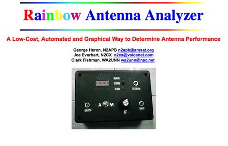 A small and inexpensive measurement device designed to determine antenna performance across the amateur bands through use of automatically collected SWR readings
 -
 This Multiband Cubical Quad antenna a boomless Quad design with glass-fibre arms and a single coax wire connected to a remote antenna switch. This aerial work on 8 bands and has a 60-degree beam width. Despite achieving critical technical requirements, the antenna's three-dimensional structure presents obstacles, such as installation issues on fixed towers and risk of frost damage. The spider framework is built of stainless steel, with a compact 18-inch boom and strong angle iron arms. Tait use a variety of methods to fasten element wires and suggests placing them on the outside of the spreaders for improved insulation. The use of nylon twine or parachute cord between key attachment points allows for adjustable separation between pieces.
 -
 A half sloper antenna for 160 meter band Italian translation of a WD8DSB article appeared in a QST issue during 1998. This article presents a **Reduced-Size Half Sloper Antenna for 160 Meters**, designed for amateur radio operators with limited space. By utilizing a 40-foot tower or a tree, you can build an efficient antenna that slopes down, achieving a 2:1 SWR bandwidth of 120 kHz. This innovative design allows for effective communication on the "Top Band," making it ideal for winter DXing.
 -
 Over 40 years of experience inform the reviews and commentary presented on Dave's Radio Receiver Page, covering a wide array of radio receivers and transceivers. The resource details specific models such as the **ICOM IC-R8600** SDR Communications Receiver, which is lauded as Icom's best wide-band receiver, even surpassing the IC-R9500 in performance. Other notable reviews include the ICOM IC-7300 HF Transceiver, highlighting its direct sampling SDR technology and spectrum scope capabilities, alongside numerous models from Japan Radio Co. (JRC), Kenwood, Yaesu, and various portable shortwave receivers. The content provides practical insights into the performance and characteristics of each radio, often drawing comparisons between models. For instance, the early issues with the AOR AR7030 receiver's Bourns mechanical encoders are thoroughly documented, including AOR's eventual switch to higher-quality Alps encoders. The page also features reviews of antennas like the MFJ-1026 Noise Canceling Signal Enhancer and various power supplies, offering a holistic view of radio monitoring setups. The author's "2 ear / 2 eye method" emphasizes real-world listening experiences over laboratory measurements, providing a unique perspective on equipment utility.
 -
 The ZS6BKW multiband HF antenna, a design by ZS6BKW (G0GSF), functions effectively on multiple HF bands without requiring an Antenna Tuning Unit (ATU) for 40, 20, 17, 12, 10, and 6 meters. This antenna, approximately **27.51 meters** (90 feet) long with a 12.2-meter (40-foot) open-wire feeder, is a direct descendant of the _G5RV_ but offers superior multi-band resonance. It can be deployed as a horizontal dipole or an inverted-vee, with the latter requiring only a single support and maintaining an apex angle of at least 90 degrees to prevent signal cancellation. Performance data, recorded with an MFJ Antenna Analyser, indicates SWR values of 1:1 on 7.00 MHz (40m) and 14.06 MHz (20m), with SWR below 1.3:1 on 17m, 10m, and 6m. While primarily designed for these bands, the antenna can be adapted for 80m, 30m, and 15m with an ATU, preferably at the balanced feeder's base. The use of 450-ohm twin-lead for the feeder is recommended over 300-ohm for improved strength and reduced losses, especially in adverse weather conditions. This design, originally published in _RadCom_ in 1993 and featured in Pat Hawker’s "Antenna Topics," provides a compact and efficient solution for HF operation, particularly for those with limited space or resources.
 -
 AEA Technology Inc. is a pioneer and leading manufacturer of RF and cable test equipment for the wireless, Telco, CATV, NMR & MRI, RFID, telemetry, aviation, commercial, military, and two-way radio industries. Produces SWR Meters, Pre Amplifiers, filters, power meters and antenna testing products
 -
 The **NW3Z** optimized wideband antenna designs, originally presented at Dayton 2001, detail Yagi configurations for the 20-meter, 15-meter, and 10-meter amateur radio bands. This resource provides access to the design files, likely containing critical parameters such as element spacing, element lengths, and boom dimensions, which are essential for replicating these directional antennas. The designs focus on achieving wide bandwidth, a desirable characteristic for contesters and DXers operating across a significant portion of each band. The content specifically references "nw3z-Antenna-DesignsDownload," indicating that the core information is available as a downloadable file, presumably in a format suitable for antenna modeling software or direct construction. Such files typically include **NEC models** or similar data, allowing for performance analysis and optimization before physical construction. The emphasis on "optimized wideband" suggests design considerations for SWR bandwidth and gain characteristics over a broader frequency range than typical narrow-band Yagis. The resource serves as a direct source for specific, proven antenna designs from a known amateur radio antenna designer, offering practical data for hams interested in building high-performance Yagi arrays for HF.
 -
 Antennas, base mobile scanner and vhf antenna, coax cables, coax switch, Lightning Arrestor, mounts, power supply, speakers and wattmeters