Search results
Query: build a balun
Links: 40 | Categories: 1
Categories
-
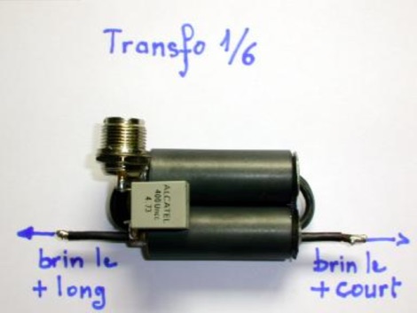 How to easily home-brew baluns even in strange formats 1/1 - 2/1 - 4/1 - 6/1 - 9/1 - 12/1 et 16/1 for bands from 1.8 to 30 (50) MHz in french
 -
 Build a portable VHF yagi antenna for 2 meters. All you need is two rabbit ear antennas from Radio Shack, two CATV baluns, four feet of 3/4 CPVC pipe with one tee.
 -
 GM4JMU shortened dipole for 40 meters band. This article illustrates in detail how to build a resonant antenna for 7.030 MHz. Cut two 10.25-meter pieces of insulated wire, wind 40 turns of wire onto plastic tubing, and connect the wire to a central insulator using a choke balun built of RG174AU coax and a ferrite toroid. Once built, the antenna is adjusted by altering the wire length to produce the lowest Standing Wave Ratio (SWR) for best performance. The guide emphasizes careful building and adjustment for the best results.
 -
 Presents a practical design for a **crossed-dipole turnstile antenna** specifically engineered for 2-meter Amateur Radio Direction Finding (ARDF) events. The author, WB6RDV, details a robust, omnidirectional, horizontally-polarized antenna, addressing the international ARDF rules requiring such characteristics at a height of two to three meters above ground. This contrasts with the vertical polarization often used in Southern California, highlighting the design's adherence to specific event requirements. The electrical design employs a classic crossed-dipole with a 75-ohm phasing section, resulting in a slight impedance mismatch and an SWR of approximately 1.3:1 with a 50-ohm feedline. Construction utilizes readily available and inexpensive PVC plumbing components and 1/8-inch bronze welding rod for elements. The guide provides step-by-step instructions for mechanical assembly, including drilling element holes at precise 90-degree spacing and preparing the RG-179 matching section. WB6RDV shares insights from his own build experience, discussing the use of plated brass versus aluminum spacers for element attachment and the effectiveness of crimping as an alternative to soldering. The document also covers final assembly, including the integration of ferrite beads as a choke balun and options for weatherproofing and alternative mounting configurations, emphasizing the adaptability of the design for other VHF bands through scaling.
 -
-
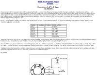
 Step-By-Step Construction of a 4:1 Current-Type Guanella Balun by W1CG
 -
 The 30/40 meter **vertical antenna** project by IK4DCS details the construction of a shortened, self-supporting design, reaching a total length of 5 meters. The antenna incorporates a linear loading section and a coaxial cable trap for 30 meters, based on the "Antenne Volume 2°" text by Nerio Neri (page 223). The design uses six radials, three for each band, positioned at approximately 90° inclination and at least one meter above the roof or ground, connected via a 1:1 balun at the feed point. Mechanical construction utilizes aluminum tubing, with a 2.30-meter primary radiator section (30 mm diameter) joined to a second part using a Teflon insert and a PVC sleeve for rigidity. The linear load, approximately 3.70 meters long, accounts for a 30% physical shortening of the quarter-wave element. A capacitive load, made from three 50 cm radials, is integrated into the 40-meter top section for fine-tuning. Final adjustments involved radial inclination for 40 meters, as initial testing showed increased SWR and interference on 30 meters due to nearby resonant structures. The author emphasizes the importance of clear space for optimal performance and provides drawings and photos to clarify the build process.
 -
 One common challenge in antenna systems is mitigating common-mode current on the feedline, which can distort radiation patterns and introduce RF in the shack. This project details a 1:1 balun design that ingeniously avoids traditional ferrite beads, often a costly component, by substituting them with steel wool. The steel wool, when integrated into the balun's construction, effectively attenuates unwanted RF on the outer braid of the coaxial cable, ensuring that the antenna radiates efficiently and as intended. The construction involves winding coaxial cable through a PVC former, with the steel wool strategically placed to provide the necessary common-mode impedance. This method offers a practical and economical alternative for hams looking to build effective baluns without the expense or availability issues associated with ferrite cores. The design principles focus on creating a balanced feed to the antenna, crucial for optimal performance of dipoles and other balanced radiators. Experimentation with such designs can lead to improved field results, particularly for those operating with limited budgets or seeking innovative solutions for their antenna systems. The simplicity of using readily available materials like steel wool makes this a compelling build for many radio amateurs.
 -
 Contruction manual to build a 4:1 balun, it has good performance from 160 through 10 meters.
 -
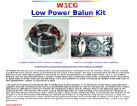
 Build a Low Power 4:1 Balun , by Charles Greene, W1CG with full-color, full-resolution graphics from the pages of QRP Homebrewer
 -
 In this designs G8ODE explains different methods to builds a choke balun
 -
 Presents a detailed construction guide for a **Quadrifilar Helix Antenna** (QHA) optimized for 137 MHz, specifically for receiving weather satellite transmissions. The resource outlines the author's experience building previous QHA designs, highlighting challenges with tuning and nulls, and then focuses on a refined design by John Boyer, documented by Steve Blackmore, which proved easier to build and yielded superior reception. The guide provides precise element dimensions, including 1.5m of 32mm PVC pipe for the mast and 8mm soft copper tubing for the helix elements. It specifies lengths for horizontal tubes (190mm, 90mm) and helix elements (903mm, 1002mm), along with instructions for drilling, assembly, and forming a **balun** by wrapping RG58 coax around the mast. The text emphasizes critical steps like ensuring elements are square and twisting in the correct direction to avoid phase issues. It includes references to original QST articles by Buck Ruperto (W3KH) and the WxSat program for decoding satellite transmissions, contextualizing the antenna's purpose. The article concludes with a sample NOAA 12 image from September 1998, demonstrating the antenna's reception capabilities.
 -
 The ZS6BKW antenna, a popular multiband wire antenna, offers improved band matching compared to the traditional G5RV. This construction guide details the process, beginning with specific dimensions: 13.11 meters (43 feet) for the 450-ohm ladder line and initial dipole arm lengths of approximately 14.8 meters each. It emphasizes the critical role of an _antenna analyzer_ for accurate tuning, particularly for determining the velocity factor of the ladder line and achieving a 1:1 impedance match. The article outlines the materials required, including a 1:1 current balun, 450-ohm window line, wire for the dipole arms, and a 50-ohm non-inductive resistor for testing. It provides a step-by-step procedure for cutting the ladder line to its electrical half-wavelength, explaining how to calculate the velocity factor using measured and free-space frequencies. For instance, a measured 50-ohm impedance at 12.54 MHz with a calculated free-space half-wavelength frequency of 11.44 MHz yields a velocity factor of 0.91. Final adjustments involve hoisting the antenna to its operational height and fine-tuning the dipole arm lengths to achieve optimal SWR, specifically targeting 14.200 MHz. The _ZS6BKW_ design is noted for its performance on 80m, 40m, 20m, 10m, and 6m, though it is not optimized for 15m operation. The author, _VK4MDX_, shares practical tips for durable construction using stainless steel wire and cable clamps.
 -
 A balun is a MUST for dipoles or similar antennas when they are feed with coaxial cables. Many hams connect the center conductor of the coaxial cable to one side of the dipole, and the shield to the other. Wrong!
 -

-
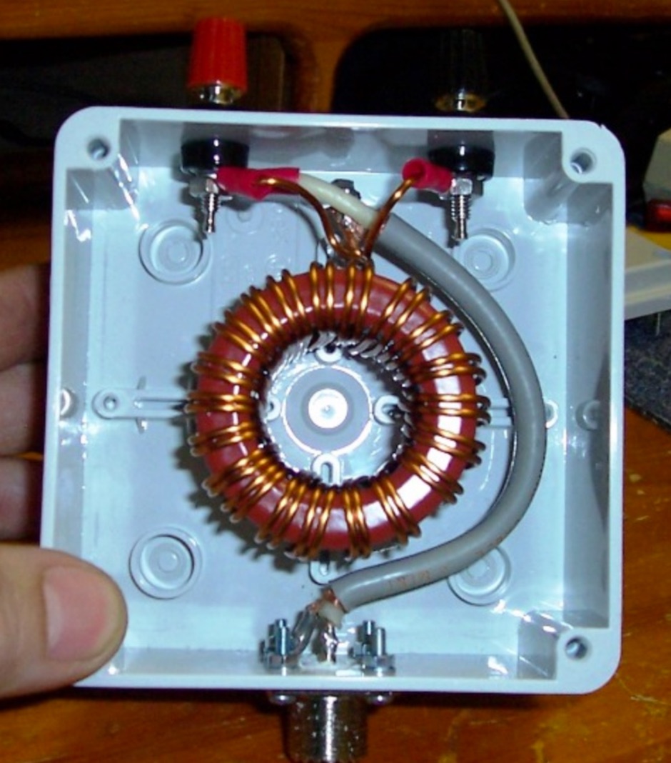
 Optimizing a G5RV or ZS6BKW multiband wire antenna for HF operation often involves addressing common SWR issues and understanding feedline characteristics. This resource chronicles the construction and performance evaluation of a G5RV, initially built for 80m, 40m, 15m, and 10m bands, by a newly licensed Foundation operator. The author details the selection of materials, including 3.5 mm stainless steel wire for the doublet arms and enameled copper wire for the open-wire feeder, and the initial decision to omit a balun based on common online information. The narrative highlights the initial disappointing performance, characterized by high receive noise and poor signal reports on 80 meters, despite the transceiver's internal ATU achieving a 1:1 match. This led to experimentation with a coax current balun and further research into G5RV myths, such as SWR claims and the necessity of a balun. The author then describes modifying the antenna to the ZS6BKW configuration, which involves specific changes to the doublet and feedline lengths, and integrating a 1:1 current balun wound on a ferrite toroid. The modifications resulted in improved reception and transmit performance across the bands.
 -
 Italian page about a home made a 1 to 40 balun with pictures and measurements on HF bands.
 -
 A DIY guide to build your own compact multiband HF antenna based on the G3TXQ version using a 1:4 balun. This article includes the full part list and instructions to assembly, including the center plate.
 -
 Building a 1:1 balun, aka un-un, with an Amidon Ferrite toroid core T 200
 -
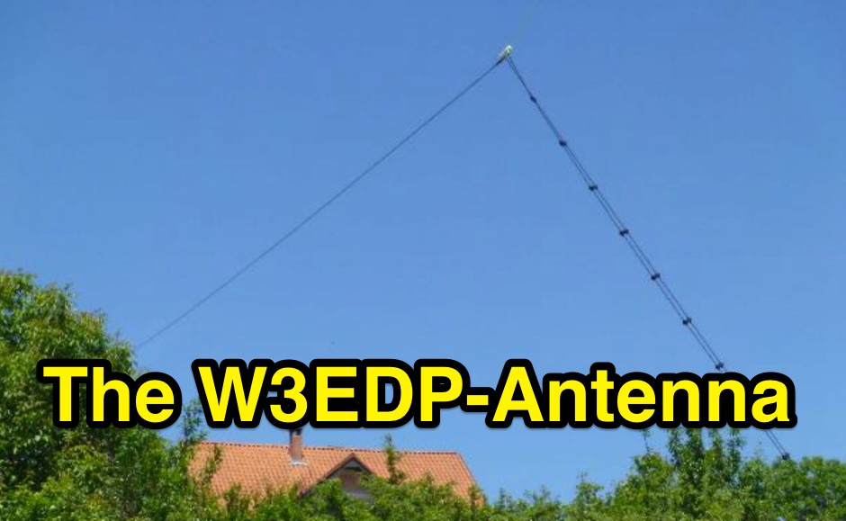 Hints for building a W3EDP-Antenna, includes the construction of the 1:4-balun by DK7ZB
 -
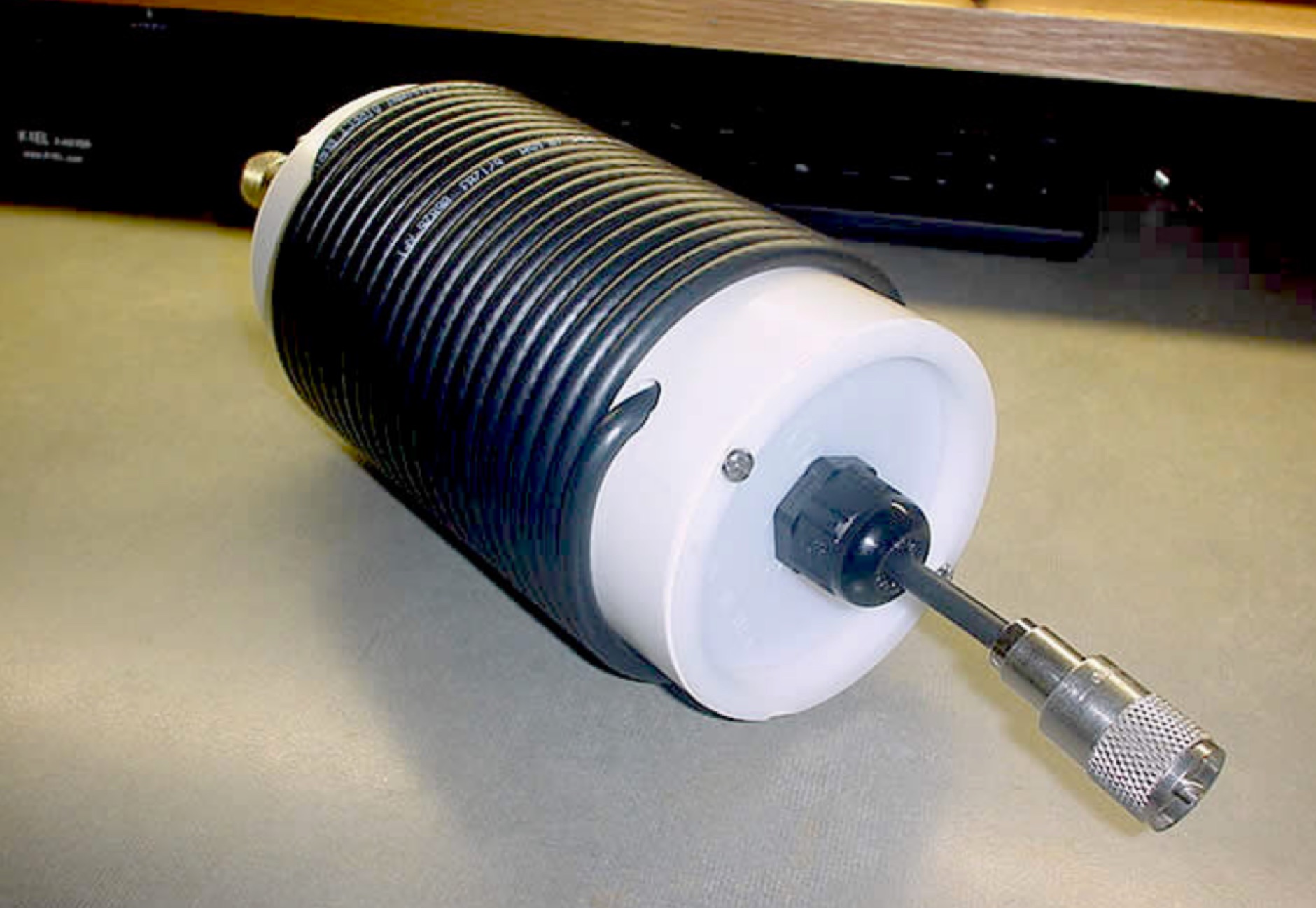 The main function of the Ugly Balun is to help eliminate rf currents from flowing on the outside of coaxial cable using the principle of choke action.
 -
 In this experiment the autor is going to explore the use of a 1:64 matching network on the End Fed Long Wire Antenna. Experiment will consist in build a 80-40-20-15-10 meter End Fed Long Wire Antenna with a 1:64 matching network from the documentation available on the internet
 -
 Building a Windom HF Antenna. A PDF file presentation about homebrewing a windom antenna for the HF bands with formulas for 40 and 80 meters bands and step by step guide on making a 4:1 balun to feed the antenna.
 -
 Constructing a high-power 70cm solid-state amplifier presents unique challenges, particularly when aiming for 500 watts output using modern LDMOS devices. This resource details the author's experience building a 70cm amplifier based on a _Freescale MRFE6VP5600H_ transistor, initially from an RFHAM kit. It meticulously outlines the necessary modifications to achieve advertised performance, including optimizing input and output matching, correcting bias circuitry, and ensuring proper output balun connections for stability. The author shares specific adjustments, such as trimming the prototyping board for better transistor fit, drilling additional mounting holes for improved heat sinking, and replacing original matching capacitors with a single _20pf MIN02 metal mica_ for superior output. A critical fix involved jumpering gate decoupling pads to balance the push-pull transistor halves, which increased output to 580W and improved IMD. The resource also highlights a crucial correction to the output balun connection, initially reversed in the _Dubus_ article schematic, which resolved intermittent stability issues. Test results are provided, showing input power, output power, and drain current at 50V, demonstrating the amplifier's performance after modifications. This practical account offers valuable insights for hams undertaking similar high-power UHF amplifier projects, especially those working with LDMOS devices and kit-based constructions.
 -
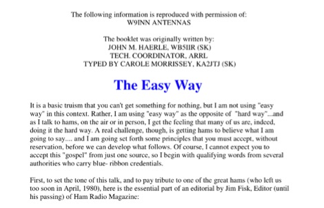
 Presents a construction project for a 1:1 current balun, specifically detailing the _Sorbie Balun and Bottle Choke_ design. The resource outlines the winding technique, employing 4+4 turns of mini coaxial cable on a large ferrite core, and provides insights into the physical assembly. It includes specific material recommendations, such as the type of ferrite and coaxial cable, crucial for achieving the desired impedance transformation and common-mode current suppression. The content covers the practical steps involved in building the balun, from preparing the coaxial cable to securing the windings on the ferrite toroid. It also discusses the integration of the balun into an antenna system, emphasizing its role in maintaining pattern integrity and reducing RF interference in the shack. The resource offers a clear, step-by-step approach, making the project accessible for homebrewers. Illustrations and photographs accompany the text, visually guiding the builder through each stage of construction. The article concludes with performance expectations and considerations for deployment, ensuring the constructed balun functions effectively across the intended frequency range.
 -
 This document is a must read for anyone considering building a good low cost HF multi-band antenna system. The author combine in this document four important ingredients to produce simple but effective antenna system, like antennas of non resonant length, line attenuation, the transmatch and the balun
 -
 1500 watts PEP SSB is the power handling capability of the MFJ-989C HF Antenna Tuner, a popular choice among amateur radio operators. Users have shared a wide range of experiences, with some praising its durability and performance over decades of use, while others criticize its build quality and accuracy. The tuner features a built-in dummy load, SWR-wattmeter, and a balun for balanced line feeders, making it versatile for various antenna setups. However, discrepancies in RF power readings and SWR measurements have been noted, with some users finding the dual scale meter to be off by about 20% compared to a Bird wattmeter. Long-term users report that the MFJ-989C performs well with proper antenna setups, but caution against tuning at high power without initial adjustments at lower power levels. Some have experienced issues such as arcing when exceeding 400 watts, while others have had no problems even at higher power levels. The roller inductor and capacitors are functional, though some users have had to perform maintenance like tightening screws or cleaning components to ensure reliable operation. Despite mixed reviews, the MFJ-989C remains in production, suggesting continued demand. It's a tuner that requires careful handling and possibly some DIY fixes to achieve optimal performance.
 -
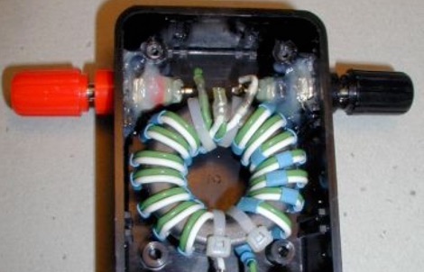
 This Guide helps you to build the 1:2 BalUn 600 Watts DIY kit step by step. If a delta-loop or quad-loop antenna is powered with a coax cable from the transceiver it is necessary to use a 1:2 BalUn. This 1:2 BalUn uses a symmetrical 1:2 impedance transformer.
 -
 This article presents a comprehensive guide to constructing a multiband vertical wire antenna. The design features parallel wires for various bands, all connected to a single balun, ensuring ease of assembly and adjustment. Materials required include a fishing rod, PVC tubing, and inexpensive wire. The antenna is lightweight, cost-effective, and suitable for field use or as an additional home setup. Detailed instructions and diagrams are provided to facilitate successful construction and optimal performance across multiple frequencies.
 -
 A balun is a MUST for dipoles or similar antennas when they are feed with coaxial cable. From the RF point of view, the shield can be modeled as two conductors, the internal shield (the real shield, this is, ground) and the external shield, who is really far to be ground. In this way, your dipole has 3 arms, the two from the dipole and the coaxial cable shield (external face)
 -
 This type of antenna is a popular antenna design as the performance is very good across the HF bands and requires little or no tuning. It’s a dipole fed off center with a 4:1 balun at the offset feed point. The antenna shown covers 80, 40, 20 and 10 meters. The formula can also be used to adjust the overall length to cover more or fewer bands and the resulting overall length. 160-10m, 80-10m or 40-10 meters depending on your available space. Other bands will require a tuner.
 -
 This article describes a multi-band antenna design for amateur radio enthusiasts by G3FEW. The antenna is designed to cover at least five HF bands with low SWR and without the need for an ATU. It is also designed to be easy to construct and adaptable for different locations. The antenna is a full-wave dipole with traps at the quarter-wave points. The traps are used to tune the antenna to different bands. The antenna can be fed with a 4:1 balun. The article includes instructions for building the antenna, as well as information on the theory behind its operation. The author also discusses the results of his tests with the antenna. This multi-band antenna is a well-designed and versatile antenna that can be used by amateur radio enthusiasts on a variety of bands. It is relatively easy to construct and can be adapted for different locations.
 -
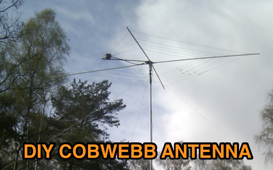
 The CobWebb antenna project is a compact, multiband HF solution ideal for amateur radio operators. Covering 14-28 MHz, it features a square dipole array with near-omnidirectional coverage and unity gain. This guide details a DIY approach, using a 1:4 current balun for impedance matching. Construction involves aluminum and fiberglass tubing, with optimized element tuning for SWR performance. Weather resistance improvements and resonance shift considerations are also discussed. Build your own CobWebb antenna for an efficient, space-saving HF experience.
 -
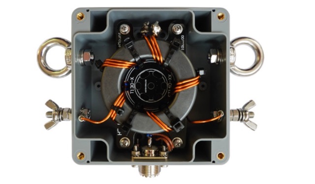
 This PDF guide provides step-by-step instructions on how to build a Bunnings Balun for your ham radio antenna. A balun is essential for matching the impedance between your antenna and radio, improving signal transmission. The guide is perfect for hams looking to enhance their radio setup on a budget. Follow the detailed instructions to create your own balun using easily accessible materials from Bunnings or any hardware store.
 -
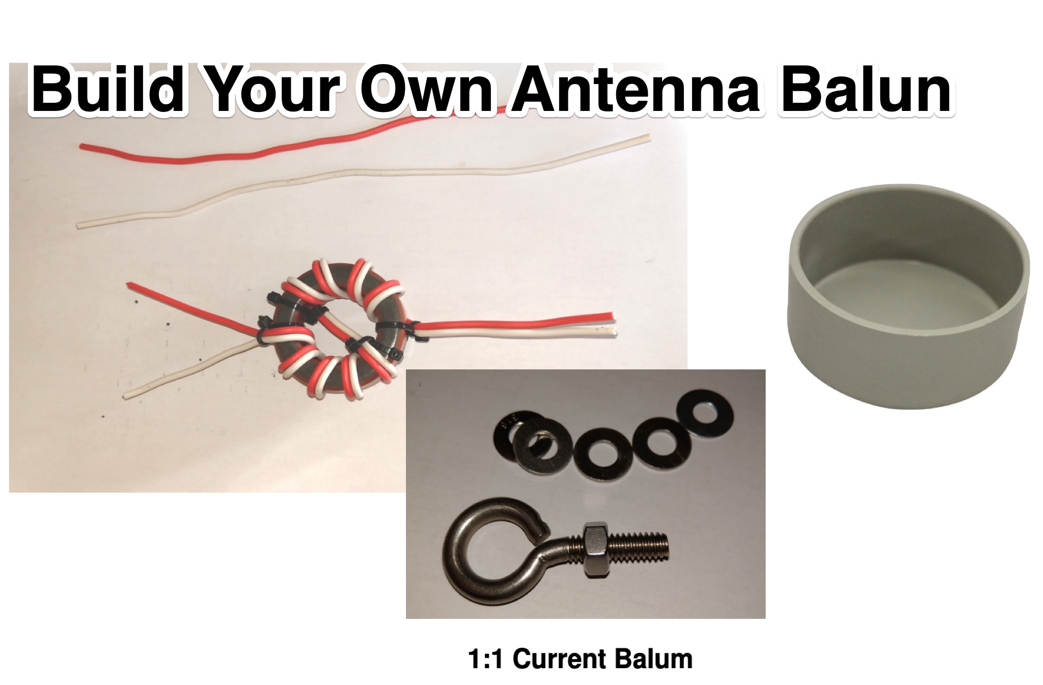
 The UniBalun is a PCB for building a lightweight antenna transformer (Balun) or impedance converter (UnUn) for low power radios. By soldering jumpers and a toroid core, you can create a 1:1, 1:4 Balun or 1:49, 1:9 UnUn. The latest revision (1.2) includes improved pads and supports both BNC and SMA connectors. Build instructions are available for German speakers.
 -
 This project involves constructing a dual-band Moxon antenna, optimized for ham radio enthusiasts, with functionality on both the 10-meter and 6-meter bands. The antenna is designed to operate using a single 50-ohm feedpoint, acting as a mini-beam on 28 MHz (10 meters) and as a 2-element Yagi on 50 MHz (6 meters). Performance-wise, it offers a 4.0 dBd gain on 10 meters and 4.3 dBd on 6 meters, with impressive front-to-back ratios of 30 dB and 11 dB, respectively. Builders like Aleks (S54S) and Marcio (PY2OK) have successfully brought this design to life using the provided specifications. Aleks noted that bending the corners of the structure proved especially useful during assembly. The project comes with a detailed parts list, highlighting the use of aluminum tubes with different diameters and lengths to form essential components like the reflectors and radiators. For those looking to fine-tune the antenna, adjustments can be made by altering the length of certain parts that fit into larger tubes. The feeding system is equipped with a balun to accommodate different power levels, making the design versatile enough to handle outputs of either 300 watts or 1 kilowatt.
 -
 This DIY homebrew project provides a durable, weatherproof center connector for dipole antennas, ideal for HF setups like 40m wire dipoles or inverted-V designs. Made from PVC pipe and an SO-239 UHF connector, it ensures strong support and room for a current balun. With simple drilling and assembly, it offers a cost-effective alternative to commercial options. Perfect for amateur radio operators, this dipole antenna connector enhances performance while keeping costs low. A great solution for DIY antenna builders seeking reliability and longevity.
 -
 This comprehensive three-part guide examines baluns (balanced-to-unbalanced devices) and their critical role in ham radio antenna systems. The author explains how baluns prevent common-mode currents on feedlines, which can distort radiation patterns and cause unwanted RF in the shack. Various balun types are analyzed, including coiled coax chokes, ferrite-core designs (W2DU), and toroidal-wound versions (Guanella/Ruthroff). Construction techniques for 1:1, 4:1, 6:1, and 9:1 current baluns are provided with practical guidance on wire selection, winding methods, and ferrite core properties. The article emphasizes that proper balun implementation is essential for optimal antenna performance, especially with directional arrays.
 -
 Learn how to build a simple transmitter called the 'Easy Ten' that can be easily heard at a distance of 10 miles using a random length wire antenna thrown into a tree. This article focuses on working with frequencies in the 3.5 and 7 MHz range without the need for complex setups like coax lines or baluns. The author shares their experience of making contacts across the Pacific Ocean and the United States using just one watt of output power and simple antennas. Discover how to optimize signal output using a homemade level meter made from a DC microameter and a germanium diode.
 -
 This project describes a high-performance EME antenna array consisting of two home-designed 9-element Yagis, each about 2.5 wavelengths long, combined into a 25-ohm system and matched to 100 ohms using 9/4λ sections of 50-ohm coax. The array supports rotatable polarity from 0° to 180°, allowing both horizontal and vertical polarization to optimize moonbounce performance under varying conditions. Despite operating for years without a balun—something another designer called “disastrousâ€â€”the system has delivered strong results, including copying very weak DX such as VK3KH at about -25 dB with only 120 W (around 2 kW ERP). The builder continues to refine the mechanics, having installed new gear motors and an upgraded follow-up control system in 2011.