Search results
Query: calibration
Links: 44 | Categories: 1
-
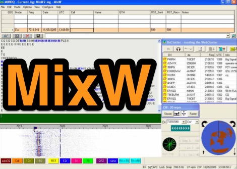 Official MixW website where you can download latest version and options for MixW, a widely used multimode software suite for amateur radio operators. The website provides access to various versions of the core MixW application, including legacy releases like Mix 2.21 for MS DOS and more recent iterations up to MixW version 3.2.105. Users can also obtain essential add-ons such as the **Olivia** support DLL, **Q15X25** support DLL, contest DLLs, and serial port emulation drivers. Detailed instructions are provided for Olivia mode operation, emphasizing the critical need for sound card sample rate calibration to ensure proper decoding and signal placement within specific frequency grids to minimize QRM. The page also links to external resources for localized help files in Spanish, Italian, French, German, and Polish, catering to a global user base. An alternative download page by G3VFP is also listed. MixW supports new transceivers for CAT control, including Yaesu FT-991, FT-1200, FT-3000, and Icom IC-7100, IC-7300, IC-7410, IC-7851. It also features an online callbook via QRZ.com.
 -
 The project details a DIY SWR/Wattmeter designed around an _Arduino Uno_ shield, providing capabilities to measure RF power from 2 to **200 watts** and Standing Wave Ratio (SWR) for HF amateur radio bands. This construction features a compact design, integrating the measurement circuitry directly onto a custom PCB that interfaces with the Arduino Uno microcontroller. Key components include a directional coupler for sensing forward and reflected power, precision rectifiers, and analog-to-digital conversion for processing RF signals. The Arduino firmware handles calibration, calculations, and displays the results on an integrated LCD, offering real-time feedback on antenna system performance. The design prioritizes simplicity for homebrewers. Performance specifications indicate accurate readings within the **2-200W** power range, suitable for typical QRP to medium-power HF operations. The project provides schematics and a basic overview of the software logic.
 -
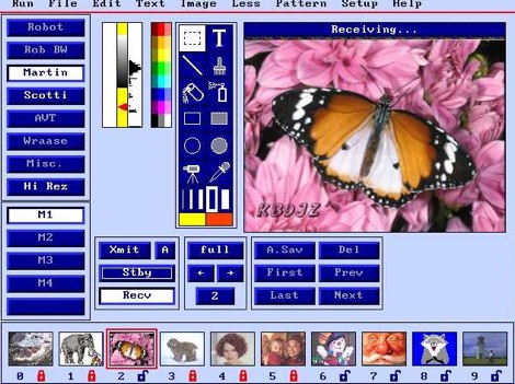 Freeware MSDOS SSTV program by WB2OSZ, Automatic Calibration, Automatic Fine Tuning, Widest Variety of File Types
 -
 Demonstrates _Freq51_ and _Specgrm2_, two analysis programs from the Biomedical Ultrasonics Laboratory at the University of Michigan, available for DOS or Linux. The _Spectrum Analyser (Freq51)_ provides power spectrum levels as a function of frequency, configurable for absolute values (e.g., dB re 1 volt) with sound card calibration. _Spectrogram (Specgrm2)_ generates a real-time, full-screen spectrogram (sonagram) with various color options. These programs analyze incoming signals in real time, not stored files, and offer extensive settings for sampling rate, FFT points, and averaging time, making them highly versatile for acoustic analysis. The DOS version of _Freq51_ and _Specgrm2_ can operate under Windows 95, requiring users to configure sound card switches via a text file. The resource also briefly mentions other acoustic analysis software like Gianni Pavan's DOS-based bioacoustic tools, _Gram_ by R.S. Horne for Windows, _SASLab_ (Light and Pro versions), _Cool Edit_, and _GoldWave_, providing a comparative overview of available tools for real-time and file-based spectral analysis and waveform manipulation.
 -
 This project shows how to build a 50-ohm dummy load using non-inductive resistors, oil for heat dissipation, and a simple assembly process. It enables accurate transmitter tuning, testing, and power measurement across LF to UHF bands. The setup allows meter calibration by measuring peak voltage, applying diode drop correction, and calculating RMS voltage and power precisely. Parts are inexpensive and widely available. With proper assembly, this dummy load offers extended service life, accurate readings within 2%, and a reliable alternative to costly commercial wattmeters for amateur radio applications.
 -
 Demonstrates the construction of a **homebrew spectrum analyzer** designed by Wes Hayward, W7ZOI, and Terry White, K7TAU, enabling radio amateurs to build a capable test instrument without significant expense. The resource details a _double-conversion superheterodyne_ circuit, employing intermediate frequencies of 110 MHz and 10 MHz, and covers essential blocks such as the time base, logarithmic amplifier, resolution filters, and local oscillators. It highlights the use of hybrid and monolithic ICs, including mixers, amplifiers, and VCOs, to simplify construction while maintaining performance. The design supports useful measurements in the 50 kHz to 70 MHz range, with methods outlined for extending capabilities into VHF and UHF. The authors emphasize that this analyzer, while simple to build, is intended for serious measurements, requiring careful control of signal levels to avoid spurious responses. It uses an oscilloscope for display, with specific instructions for calibration and adjustment of various stages, including the log amplifier and IF gain. The guide provides detailed schematics and component lists for each section, such as the 110 MHz triple-tuned band-pass filter, which achieved **90 dB** image rejection, a significant improvement over double-tuned circuits. Practical advice on alignment and troubleshooting is included, drawing on the authors' extensive experience in RF circuit design.
 -
 Details a practical QRP wattmeter construction, leveraging a simplified SWR meter design by JA6HIC. The project focuses on a forward-only power measurement circuit, providing a functional instrument for RF power levels from milliwatts up to 5 watts. It maintains a 50-ohm input and output impedance, suitable for typical QRP transceivers and antenna systems. The resource includes the schematic for the "VSW" (Very Simple Wattmeter) and outlines a six-step alignment procedure. This calibration process involves using a known RF source up to 5W, setting full-scale deflection, and marking power increments. It also addresses minimizing frequency effects on readings with a 100pF trimmer capacitor, noting that measurement error is highest at the lower end of the scale. Construction notes mention using a piece of RG-213 coaxial cable for the inductance and coupler, with the wattmeter assembled in early 2003. The author provides an example measurement showing 0.8W into a dummy load and 1W into a 3-element beam.
 -
 Constructing a functional spectrum analyzer for the 0-100 MHz range presents a significant challenge for radio amateurs, often requiring specialized components and careful calibration. This project details a homebrew spectrum analyzer design utilizing common integrated circuits like the _SA605D_ FM receiver IC and _MAR-6_ MMIC amplifiers, aiming for a cost-effective solution. The design incorporates a low-pass filter, RF amplification, a voltage-controlled oscillator (VCO) for downconversion, and multiple IF stages at 150 MHz and 10.7 MHz, with a resolution bandwidth (RBW) of 15 kHz. Critical components such as the _SBL-1_ mixer and varicap diodes are specified, alongside instructions for winding inductors and tuning filters. The analyzer's performance is discussed in terms of input level limitations, specifically the 1dB-compression point and third-order intercept point, to ensure accurate measurements and prevent component damage. The _SA605D_'s logarithmic Received Signal Strength Indicator (RSSI) output serves as the detector, driving the Y-input of an oscilloscope, while a _TL084_ op-amp generates the sweep signal for the X-input. Potential enhancements include adding a step attenuator, improving front-end filtering, and implementing switchable IF filters for variable RBW, allowing for greater versatility in analyzing RF signals.
 -
 An home made SWR meter for 2.4 GHz. A DIY SWR meter that allow precise measurements and calibration of any WiFi antenna. This is test equipment everyone who build wifi antennas should have in their shack. Article is in french and include some videos.
 -
 Accurately determining an antenna's feedpoint impedance is crucial for optimal performance, especially when experimenting with new designs or making adjustments. While SWR meters provide basic information, a full complex impedance measurement reveals the resistive and reactive components, which are essential for proper matching. Modern antenna analyzers, like the _Palstar ZM30_ or MFJ259B, simplify this task, but measurements taken through a transmission line require careful interpretation due to impedance transformation. This resource details a calibration method to precisely account for the effects of the feedline. It explains how a transmission line can significantly alter the measured impedance, illustrating this phenomenon with a Smith Chart example where an 80m antenna's [22 + j6] Ohms feedpoint impedance transforms to [82 + j45] Ohms after a 10m line. The guide demonstrates using a transmission line calculator applet, such as the one by W9CF, to reverse this transformation. It outlines the process of calibrating a specific length of RG174 coax, showing how an initial 26ft estimate was refined to **25.85ft** to accurately predict a known 22 Ohm load, significantly improving accuracy over uncalibrated results.
 -
 For radio amateurs and electronics enthusiasts maintaining vintage tube gear, having accurate documentation for tube testers is crucial. Michael Marx, WB0SND, through SND Tube Sales, provides high-quality reproductions of these essential manuals. These aren't mere photocopies; each manual is digitally scanned, cleaned of imperfections, and professionally printed on a _Laserjet 5000_ with heavy card stock covers and plastic comb binding, often making them difficult to distinguish from originals. The catalog includes instruction manuals, schematics, and roll chart supplements for a wide array of classic tube testers. Operators can find documentation for popular models such as the _Hickok 539B/C_, _AVO CT-160_, and _B&K 700_, along with military-grade testers like the _TV-7_ and _USM-118_. Many listings also offer specialized supplements for obsolete or foreign tubes, ensuring comprehensive coverage for diverse tube collections. WB0SND's offerings extend to calibration instructions and data for specific adapters like the _Hickok CA-4_ and _CA-5_, providing critical support for precise tube testing.
 -
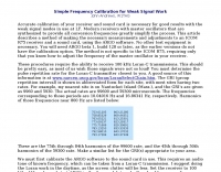 Accurate calibration of your receiver and sound card is necessary for good results with the weak signal modes in use at LF. Modern receivers with master oscillators that are synthesized to provide all conversion frequencies greatly simplify the process. This article describes a method of making the necessary measurements and adjustments to an ICOM R75 receiver and a sound card, using the ARGO software
 -
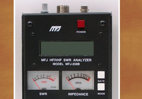 The correct way to calibrate the MFJ-259B analyzer
 -
 Gold Line, a manufacturer, provides a range of professional audio test and analysis equipment, including specific products like the **ZM1 Impedance Meter**, which is relevant for amateur radio operators needing to characterize antenna systems. The site also lists various noise sources and microphones, such as the TEF04 Mic, indicating a focus on audio signal integrity and measurement. The resource details contact information for repairs, calibration, quotations for specific products like the ZM1 and ZM1P, and technical support, with distinct email addresses and phone numbers provided for each function. This structured contact approach facilitates direct engagement with the appropriate department for specific inquiries. Operational changes effective March 1, 2019, are noted, directing users to VLDESIGN for repair and calibration, and to Partha Chen for ZM1/ZM1P quotations. Louis Pittsley is designated for technical support, with a general inquiry phone number also available, outlining the company's support infrastructure.
 -
 Spectrum manufactures very high-performance, low-cost, GPS-disciplined time and frequency reference standards for industry, scientific, calibration, broadcast and amateur operators.
 -
 Producer of meter test equipment for electricity meters testing and calibration
 -
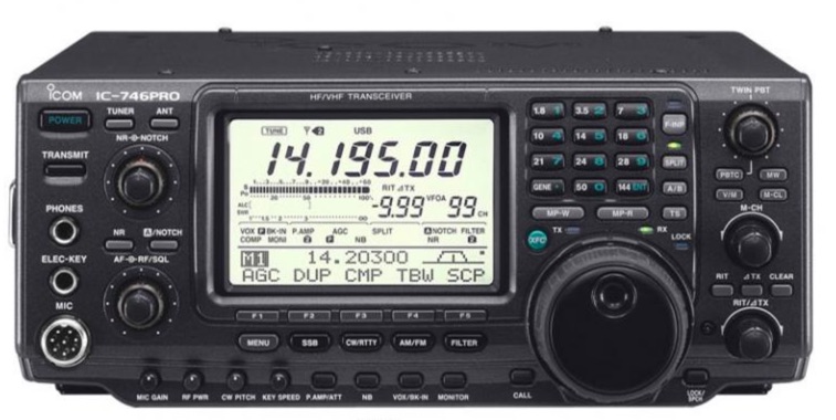 Frequency calibration is a user adjustment on the rear panel. Learn how to calibrate the IC-746 Pro.
 -
 Constructing a basic multimeter involves integrating a 0-1mA meter movement with various shunts and multipliers, selected via a switch, to create a versatile instrument capable of measuring DC volts, current, and resistance. The design outlines two main units: a primary unit handling six DC current ranges up to 1 amp and eight DC voltage ranges up to 1000 volts, alongside an internal battery for an ohms range up to 200,000 ohms. This approach allows for a practical, hands-on understanding of meter operation. An add-on unit further extends the multimeter's capabilities, incorporating a meter rectifier and switched series resistors to provide four AC voltage ranges up to 100 volts. Additional shunt and series resistors, designated Ra and Rb, are included to expand the instrument's range to 10A and 5kV, demonstrating how modular design can enhance functionality. When this add-on is in use, the main instrument is set to measure 1mA FSD, connecting via specific lugs. Component selection emphasizes precision, with 1% tolerance high stability resistors for series elements and Eureka resistance wire for shunts. The design specifies values calculated for a meter with 60 ohms internal resistance, noting that these would require modification for different meter characteristics. Experimental adjustment of shunt values is recommended to ensure accurate readings against a calibrated reference meter, reinforcing practical calibration techniques.
 -
 A 0-30 MHz step attenuator, constructed from switchable Pi attenuation pads, provides a practical tool for evaluating receiver sensitivity and calibrating S-meters. The design utilizes readily available 5% tolerance resistors, with values derived from paralleled components to achieve specific attenuation steps. A schematic (Fig 1) illustrates the circuit, including PCB pad shielding, while a table details required and actual resistor values, along with percentage differences. Measurements of voltage input versus output at various frequencies are used to calculate dB attenuation, presented in a graph (Fig 4). The resource includes formulas for determining output voltage from a known input and a comprehensive 0-40 dB voltage multiplier table, which is crucial for precise signal level management. The project also references external attenuator calculators and equations for further study. Photos (1-3) provide visual guidance for the assembled unit, showing bottom, top, and front views. The project emphasizes the use of **Pi attenuation pads** and **receiver sensitivity** evaluation, offering a hands-on approach to RF signal management.
 -
 Distributor of test and measurement and calibration instruments and provider of NIST traceable ISO/IEC 17025 accredited calibration services. Texso sells insulated tools, multimeters, insulation testers, and much more.
 -
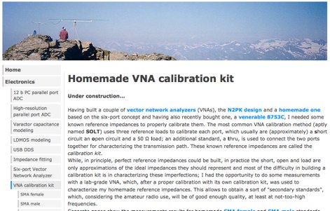 A calibration kit useful when you need known reference impedances to properly calibrate your vector network analyzers.
 -
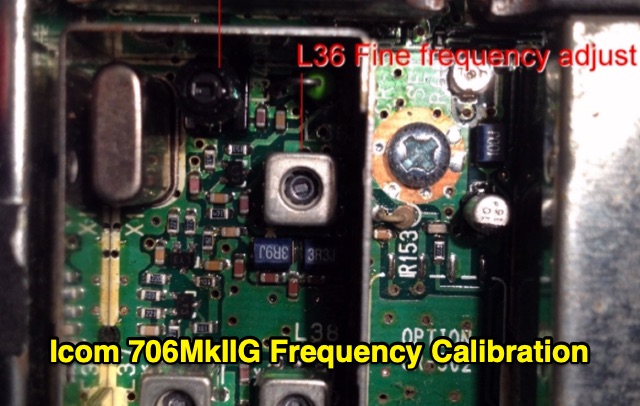 Unlike older radios, the 706 uses only one crystal oscillator (called the Master Oscillator). All other frequencies in the radio (L.O., 3-4 I.F. stages, VFO, and CW-offset) are computer-derived from the Master Oscillator. This makes it relatively simple to frequency-align the radio, so that it agrees with the Frequency Display in all modes.
 -
 Clarifies the intricate process of calibrating the _Elecraft K2_ dial, addressing common user challenges and lively discussions on the Elecraft reflector. Wilhelm, W3FPR, dissects the K2's PLL synthesizer design, chosen for its low phase noise, kit-friendly duplication, and cost-effective components. The resource emphasizes the critical role of the 4000.000 kHz reference oscillator's accuracy during CAL PLL, CAL FIL, and CAL FCTR functions, noting its dependence on temperature and crystal stability for optimal performance. Explaining the K2's frequency display, the document reveals it relies on microprocessor-driven look-up tables generated by CAL PLL for VFO values and CAL FIL for BFO values. In SSB and RTTY, these combine, while CW and CWr modes also factor in the sidetone pitch. The author details inherent limitations, such as the 10 Hz increment resolution of the dial and varying PLL step sizes—from 3 Hz on 160 meters to 10 Hz on 10 meters. BFO increments range from 20 to 35 Hz, collectively limiting practical dial accuracy to within **20 Hz** with diligent effort, or **30 Hz** for a slightly less demanding task. The guide outlines a four-step calibration procedure: setting the reference oscillator, running CAL PLL, running CAL FIL, and setting all BFOs. It highlights the _N6KR Method_ as a particularly easy and accurate approach, requiring only the K2 and a known frequency source like WWV for zero-beating, eliminating the need for external test equipment.
 -
 Enables Android users to operate various _miniVNA_ antenna analyzers via Bluetooth, USB, or Wi-Fi, providing a portable solution for RF measurements. The application supports full control over data acquisition, offering features like custom frequency range selection from 1 KHz to the VNA's full range, and automatic screen adaptation for diverse Android device resolutions. It facilitates intuitive, wizard-based calibration for both reflection and transmission modes, saving calibration data for different VNA types (Standard, Pro, Pro with Extender) to avoid repeated procedures. The software displays critical parameters such as SWR, |Z|, Return Loss, Phase, Rs, and |Xs| on 2-axis graphs or Smith charts, with multi-touch gestures for zoom and frequency shift. It includes a frequency generator mode with independent channels and attenuator control for the miniVNA Pro, along with a sweeper function. The cable data mode automatically calculates phase and loss, measures cable length from less than 1 meter to hundreds of meters, and includes a table of common coax cable velocity factors. An experimental X-tal mode measures resonance frequency, Rs, and Q. Data export options include CSV, ZPLOT, and S1P formats, with CSV import capability. The application also features an SM6ENG Audio mode for SWR tuning without visual reference and provides a miniVNA battery voltage indicator. It supports a wide frequency range, with the miniVNA Extender extending coverage up to **1500 MHz**. The application is compatible with Android version 2.2 and later, tested on devices like the _Galaxy TAB 7.7 P6800_.
 -
 The _RS Group_ (formerly Distrelec) provides a comprehensive online store for electronic components, catering to both industrial and amateur radio needs. This resource offers a wide array of parts, including semiconductors, capacitors, resistors, relays, sensors, and power supplies, essential for constructing and maintaining amateur radio equipment. The platform emphasizes efficient procurement and features various top-level categories for easy navigation, such as **Sensors** with 33 subcategories and **Relays** with 13 subcategories, supporting diverse project requirements. Beyond component sales, RS Group offers services like ISO- and DAkkS-certified calibration for over a thousand measuring devices, and e-procurement solutions for businesses. The site also promotes _DesignSpark_, a community and software suite for electronic designers, aiding in the realization of design ideas. This integration aims to provide enhanced local support and a broader product selection, facilitating everything from basic circuit builds to complex industrial automation projects.
 -
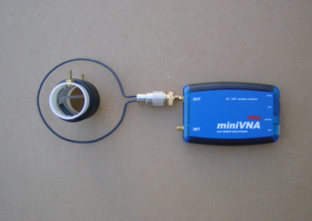 Notes on installing the miniVNA PRO software, making a calibration standard, a trap tuning loop.
 -
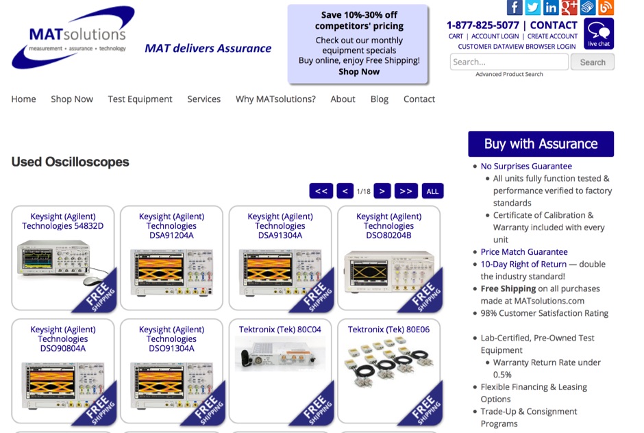 Since 1992, MATsolutions has delivered the assurance our clients need when acquiring, maintaining, and managing high-quality test and measurement equipment. Used Electronic Test & Measurement Equipment Sales, Calibration, Repair & Services
 -
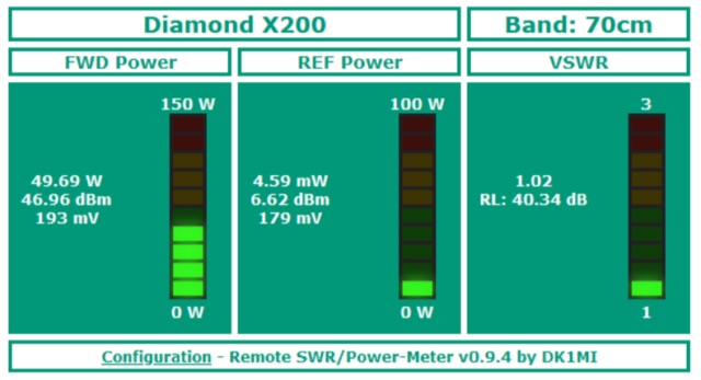 Remotely monitor the output power and SWR of your station via a web browser. WT32/ESP32 based project, combined with a directional coupler setup. It reads two voltages which are supplied by the directional couplers. From these, the respective power is calculated with the help of a calibration data table to be created by the user.
 -
 Paul McMahon presents a compact VSWR meter designed for QRP portable use, ideal for SOTA operations with rigs like the FT817. The device, constructed from readily available components, employs a simple resistive bridge for wideband performance from 1.8MHz to 52MHz, with diminishing accuracy at higher frequencies. Key features include no need for external power, simple calibration, and operation with low power levels. The design, detailed with parts lists, schematics, and construction guidelines, ensures a 2:1 worst-case VSWR to protect transceivers during antenna matching. Calibration points are set for accurate VSWR readings at various loads.
 -
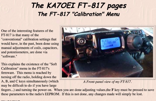 One of the interesting features of the FT-817 is that many of the conventional calibration settings that would have, in the past, been done using manual adjustments of coils, capacitors, and potentiometers, are done via software.
 -
 The document provides a detailed modification guide for the Zetagi HP201 SWR Wattmeter, converting it for HF amateur band usage. It replaces the original circuit with a Tandem Coupler based on the Sontheimer and Frederick directional coupler patent, enhancing accuracy and sensitivity. Key components include Murata toroid cores, scaling resistors, and a new calibration process. Challenges and solutions during the modification process are discussed, ensuring linear results across 160-10m bands. This guide also includes calibration instructions and theoretical insights into the coupler's operation.
 -
 How to repair and calibrate a used Bird model 43 wattmeter.
 -
 The Weather Fax plugin for OpenCPN allows you to directly open image files or decode audio faxes into images. With easy calibration, these images can be overlaid on charts. It supports image conversion in Mercator, polar, conic, and uniform coordinates and can transform any image into a raster chart. Additionally, it includes a built-in database for HF radio fax stations via SSB and another for retrieving data from meteorological websites.
 -
 An **Arduino LC Meter** provides an accessible solution for precisely measuring inductance and capacitance values, crucial for RF circuit design, filter tuning, and troubleshooting in amateur radio applications. This project details the construction of a low-cost, accurate instrument using readily available components, making it an attractive alternative to commercial units for hams and electronics enthusiasts. The build process involves assembling a resonant circuit, integrating an Arduino microcontroller for frequency measurement, and displaying results on an LCD. Key components include an Arduino Uno, a 16x2 LCD, a 74HC14 Schmitt trigger inverter, and a few passive components. The design leverages the Arduino's processing power to calculate L and C values from resonant frequency shifts. Calibration procedures are outlined to ensure measurement accuracy, which is vital for critical RF work. The project includes schematics, a parts list, and the necessary Arduino code, enabling hams to construct a functional LC meter for their workbench.
 -
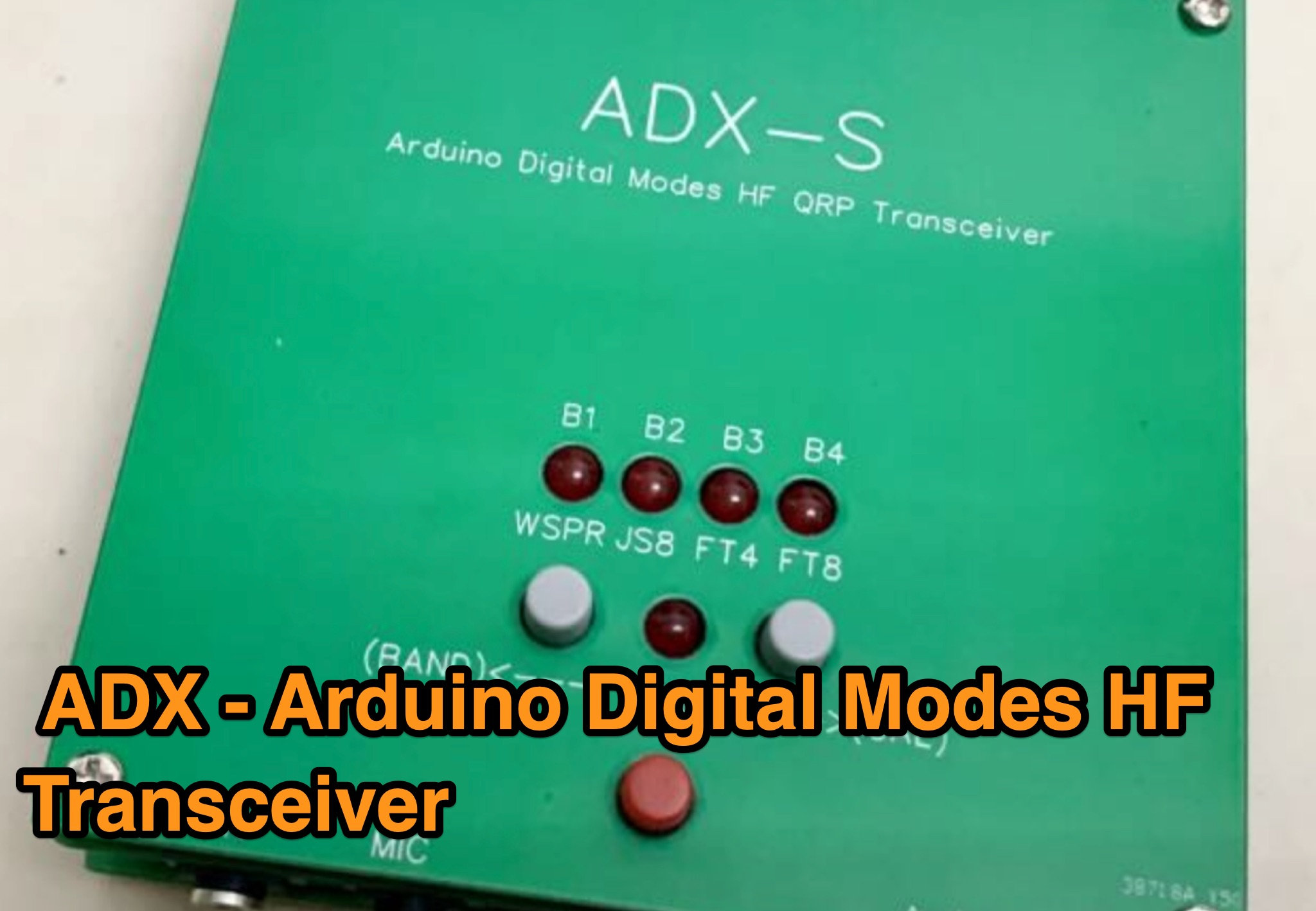 This page provides updates, manuals, and firmware for the ADX - Arduino Digital Modes HF Transceiver. Learn about calibration procedures, band display bug corrections, and important notes on the SI5351 library. The content includes a detailed build manual and firmware updates for the ADX, a mono band (actually quad band) digital modes optimized HF transceiver based on Arduino. Stay informed about the latest releases, bug fixes, and enhancements to improve your experience with the ADX transceiver.
 -
 The DIY Power Meter project utilizes the _INA226_ high-side power monitoring chip, paired with an ATtiny85 microcontroller, to measure voltage, current, and power, displaying the results on a 128x32 OLED screen. The INA226 communicates via an I2C interface and is programmed with a calibration factor based on the shunt resistance and current register LSB. The project is designed to handle a maximum current of 500mA using a 0.16ohm shunt resistor, which can be adjusted to a 0.2ohm resistor, reducing the full-scale current range to 409mA with a resolution of **12.5uA**. The shunt resistor dissipates only 33mW at maximum current, making 1/4 watt resistors suitable for the setup. The PowerMeter.ino sketch configures the shunt resistance and maximum design current, automatically calculating the calibration factor. The project can be prototyped on a breadboard using an Arduino Uno, employing the Wire library for INA226 and OLED communication, and the u8g2lib library for the OLED display. For the ATtiny85 version, the Adafruit-TinyWireM and Tiny4kOLED libraries are used. The power meter is independently powered by a 3V CR2032 cell, with power switching options including manual switches or DC switched jacks. The low-side n-channel MOSFET switch configuration is tested but introduces voltage drop issues, making manual switching a more reliable option until a suitable DC switched jack is found. DXZone Technical Profile: INA226 | ATtiny85 | OLED Display | Power Meter
 -
 The FT101ZD DDS VFO project replaces the original VFO in the Yaesu FT101Z/ZD rigs with an AD9850 DDS module, providing enhanced frequency control. It uses the original optical encoder and clarifier for compatibility, with a custom 6V power supply modification. The project includes selectable step sizes, a frequency save function, and works with both RX and TX modes. The design involves mechanical and electronic modifications, including SMD components and a custom PIC processor. Calibration ensures accurate frequency output, with further improvements under consideration.
 -
 KISS703 is a 703 Hz narrowband digital mode for amateur radio, designed for simple, low-power operation without computers. A 500 Hz pilot tone ensures frequency alignment, replaced by unique tones for 37 symbols (letters, numbers, space). Built from common discrete components, it draws about 40 mA at 12 V, ideal for SOTA/IOTA use. The receiver uses amplification, wave shaping, and a pulse-counting frequency meter for manual decoding via a calibrated meter. Transmitter and receiver calibration involves marking meter positions for each tone, enabling fully self-contained messaging with minimal hardware in portable or fixed operations.
 -
 This project features a compact, 5-LED general-purpose S-Meter, designed for use with various radio circuits. It utilizes the LB1403 IC, with alternatives like LB1413, LB1423, and others. The circuit's design allows flexibility, with one version featuring a trimpot for calibration and another without it for more compact setups. The LB1423 is preferred for its low current draw and dB-calibrated scale. This S-Meter offers an efficient, customizable solution for measuring signal strength in amateur radio applications. In Portuguese.
 -
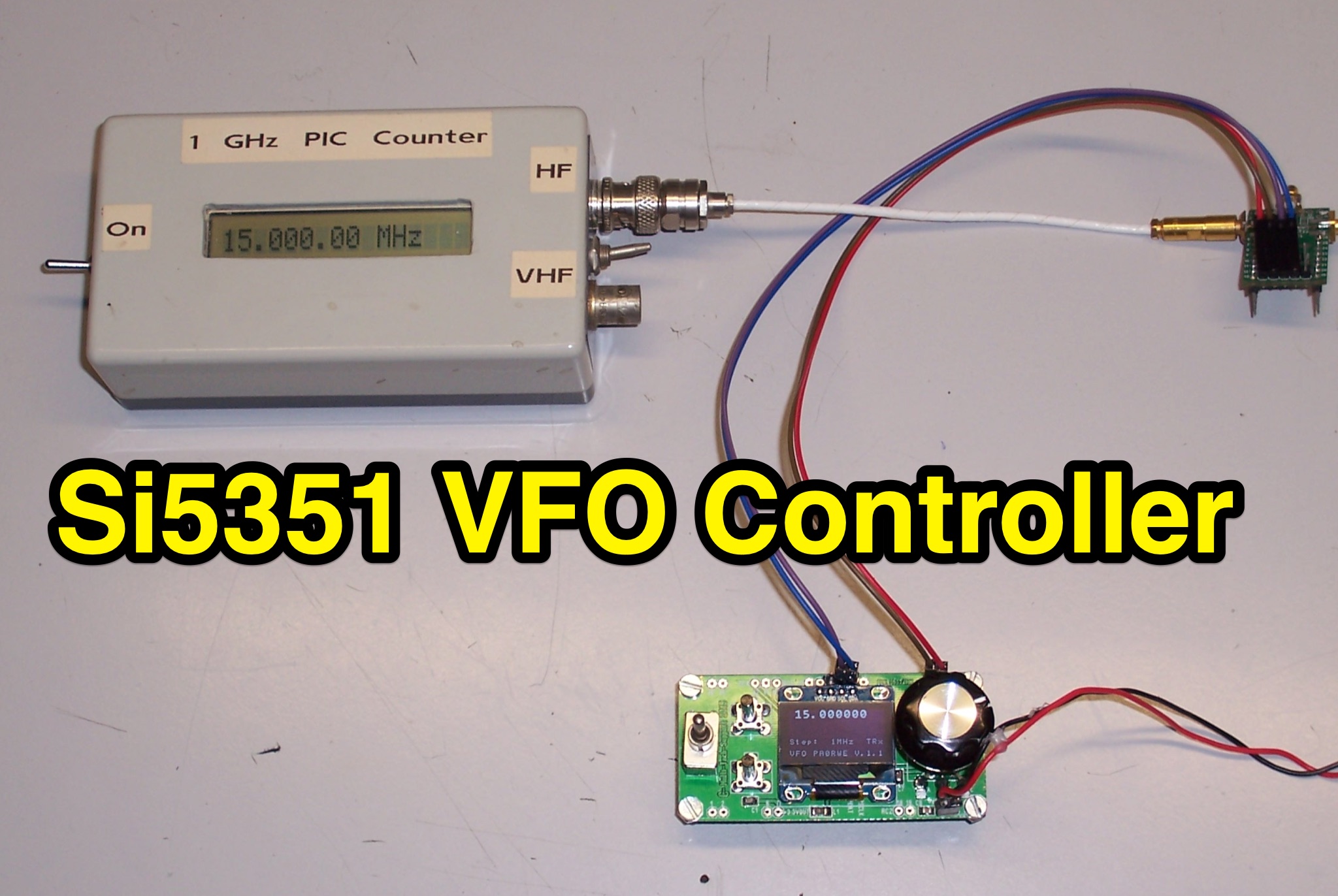 Learn how to build a VFO controller based on the Si5351 for ham radio operators. This controller consists of a PIC16F1825 and OLED SSD1306 display, with clock outputs for Tx, Rx, and IF frequencies. Features include calibration, RIT function, and the ability to tune frequencies separately. With step-by-step instructions and schematics, you can easily create your own VFO controller for your amateur radio setup.
 -
 Twenty 1-watt carbon film resistors are configured in parallel to construct a 50-ohm **dummy load** for amateur radio applications. The design incorporates a heatsink for thermal dissipation and an **SO-239 connector** for RF input, making it suitable for QRP operations. This budget-friendly project details component selection, soldering techniques, and mounting procedures, achieving a continuous power rating of 10 watts and intermittent handling of up to 100 watts across HF and VHF frequency ranges. The resource provides a step-by-step guide for assembly. This construction offers an economical solution for essential shack tasks such as antenna tuning, transmitter testing, and SWR meter calibration without radiating an RF signal. The utilization of readily available components significantly reduces the overall build cost compared to commercial alternatives, providing radio amateurs with a functional and reliable test accessory. While specific VSWR measurements are not provided, the design prioritizes practical utility for low-power transceiver diagnostics and general RF experimentation.
 -
 This resource presents a non-rigorous evaluation of the front-to-back (F/B) ratio of short Beverage antennas, specifically designed for low-band operation on frequencies such as 160, 80, 40, and 30 meters. The author, VE1ZAC, details the methodology used to measure the F/B ratio, which involves using a Millen Grid Dip Oscillator as a portable signal source. Measurements were taken by switching the antenna direction and recording S Meter and preamp readings to derive gain numbers. The document discusses the challenges faced in achieving accurate measurements and the assumptions made during the process, such as the calibration of S Meter units at 6 dB. This evaluation is particularly relevant for amateur radio operators interested in antenna performance on low bands.
 -
 ESA1 features a state-of-the-art workshop capable of performing repairs, calibrations, and restorations on antique radios, jukeboxes, and gramophones. We return your vintage equipment to you in the best and most original condition possible. ESA1 is based in Italy.
 -
 This study analyzes the antenna pattern of the Utah Amateur Radio Club's 146.760 MHz repeater following antenna relocation in 1997. Noting degraded transmission toward the north, a customized signal mapping system using a Yaesu FT-817, GPS, and software was developed to log real-time signal data. Calibration techniques extended the radio's signal range, enabling precise field measurements. The method allowed continuous signal strength monitoring while driving, revealing anomalies in coverage likely due to tower modifications. Findings helped assess and visualize the antenna’s actual radiation pattern and highlighted environmental impact on signal distribution.