Search results
Query: swr directional
Links: 28 | Categories: 0
-
 The project details a DIY SWR/Wattmeter designed around an _Arduino Uno_ shield, providing capabilities to measure RF power from 2 to **200 watts** and Standing Wave Ratio (SWR) for HF amateur radio bands. This construction features a compact design, integrating the measurement circuitry directly onto a custom PCB that interfaces with the Arduino Uno microcontroller. Key components include a directional coupler for sensing forward and reflected power, precision rectifiers, and analog-to-digital conversion for processing RF signals. The Arduino firmware handles calibration, calculations, and displays the results on an integrated LCD, offering real-time feedback on antenna system performance. The design prioritizes simplicity for homebrewers. Performance specifications indicate accurate readings within the **2-200W** power range, suitable for typical QRP to medium-power HF operations. The project provides schematics and a basic overview of the software logic.
 -
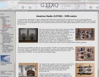
 Presents a practical design for a **crossed-dipole turnstile antenna** specifically engineered for 2-meter Amateur Radio Direction Finding (ARDF) events. The author, WB6RDV, details a robust, omnidirectional, horizontally-polarized antenna, addressing the international ARDF rules requiring such characteristics at a height of two to three meters above ground. This contrasts with the vertical polarization often used in Southern California, highlighting the design's adherence to specific event requirements. The electrical design employs a classic crossed-dipole with a 75-ohm phasing section, resulting in a slight impedance mismatch and an SWR of approximately 1.3:1 with a 50-ohm feedline. Construction utilizes readily available and inexpensive PVC plumbing components and 1/8-inch bronze welding rod for elements. The guide provides step-by-step instructions for mechanical assembly, including drilling element holes at precise 90-degree spacing and preparing the RG-179 matching section. WB6RDV shares insights from his own build experience, discussing the use of plated brass versus aluminum spacers for element attachment and the effectiveness of crimping as an alternative to soldering. The document also covers final assembly, including the integration of ferrite beads as a choke balun and options for weatherproofing and alternative mounting configurations, emphasizing the adaptability of the design for other VHF bands through scaling.
 -
 Presents the KE4UYP linear-loaded vertical antenna design, which introduces very little loss on 80 or 160 meters, achieving an overall radiation efficiency of 80% to 85%. This design addresses common pitfalls of traditional base-fed verticals by placing the majority of the current at the top of the antenna, eliminating the heavy reliance on extensive ground radial systems. The author's initial 10-meter model, only three feet tall, yielded 5/9 signal reports to Anchorage, AK, and Europe, confirming its effectiveness. The antenna incorporates both vertically and horizontally polarized radiators, with a 1/4 wavelength horizontal counterpoise located at the feed-point, near the top, to create an almost totally omnidirectional pattern with high wave angle horizontally polarized radiation. This dual polarization ensures even illumination across all take-off angles, making it effective for both local contacts and **DXing**. The vertical element is linear loaded, adding capacitance reactance and making it longer than the horizontal element to achieve resonance and raise the feed-point impedance to 50 ohms. Fine-tuning the antenna requires careful adjustment, as tower reactance can vary. The article suggests starting with 80 feet for 80m and 170 feet for 160m for the vertical wire, then trimming for resonance. Bandwidth specifications include 300 kHz under 2:1 **SWR** on 80m and 100 kHz on 160m when suspended between trees, or 150 kHz on 80m when side-mounted on a tower.
 -
 The Bruce array is a simple, often-forgotten wire antenna array that is advantageous for 80 and 160 meters, where typical gain antennas are very large. This bi-directional broadside vertical array is only 1\4 lambda high and does not require a ground system. It offers substantially greater SWR bandwidth than the half-square or bobtail curtain. A 4-element Bruce array used by N6LF showed a gain of about 4.6 dB compared to a 1\4 lambda vertical with 8 elevated radials, with a 2:1 SWR bandwidth greater than 400 kHz. The antenna is simple and its dimensions are flexible.
 -
 The **NW3Z** optimized wideband antenna designs, originally presented at Dayton 2001, detail Yagi configurations for the 20-meter, 15-meter, and 10-meter amateur radio bands. This resource provides access to the design files, likely containing critical parameters such as element spacing, element lengths, and boom dimensions, which are essential for replicating these directional antennas. The designs focus on achieving wide bandwidth, a desirable characteristic for contesters and DXers operating across a significant portion of each band. The content specifically references "nw3z-Antenna-DesignsDownload," indicating that the core information is available as a downloadable file, presumably in a format suitable for antenna modeling software or direct construction. Such files typically include **NEC models** or similar data, allowing for performance analysis and optimization before physical construction. The emphasis on "optimized wideband" suggests design considerations for SWR bandwidth and gain characteristics over a broader frequency range than typical narrow-band Yagis. The resource serves as a direct source for specific, proven antenna designs from a known amateur radio antenna designer, offering practical data for hams interested in building high-performance Yagi arrays for HF.
 -
 This PDF document, authored by KT4QW in October 2004, details the construction and modeling of a dual-band, horizontally polarized hanging rectangular loop antenna for **10 and 17 meters**. The design, adapted from *The ARRL Handbook*, utilizes _NEC4WIN95_ software for scaling and optimization, targeting a 50 ohm feedpoint impedance. The resource includes a bill of materials, step-by-step construction instructions, and a discussion of the antenna's radiation characteristics. It presents NEC-generated elevation and azimuth patterns, comparing the loop's performance to a half-wave horizontal dipole at the same height and frequency. The 17-meter element is centered at 18.140 MHz for low SWR across the phone band, while the 10-meter element is centered at 28.500 MHz. Construction involves 14-gauge stranded copper wire and Schedule 40 PVC spreaders, with the total wire length calculated by the formula: Length in feet = 1005/MHz. The feedpoint impedance can be adjusted by modifying the rectangular aspect ratio. The document specifies hoisting the antenna to at least a half-wave above ground for testing. It notes that a balun was tested and found to have no measurable effect on SWR or radiation characteristics. A 2-meter scale model is presented to illustrate the physical design, and a "rotator" string is incorporated for directional adjustment up to 90 degrees.
 -
 Based on the N2PK design, this swr meter use a stockton directional coupler
 -
 This project outlines the construction of a 3-element reversible quad antenna specifically designed for the 40-meter band. The materials required include pushup towers, pressure-treated posts, insulated wire, and various electrical components such as relays and a balun. The construction process is straightforward, beginning with the installation of the posts in a straight line, followed by the assembly of the antenna elements and their elevation to the desired height. The antenna's design allows for directional signal reception, making it ideal for operators looking to enhance their communication capabilities on the 40-meter band. The project includes detailed instructions on tuning the antenna for optimal performance, ensuring that operators can achieve the lowest SWR possible. Additionally, the design can be adapted for other bands by extrapolating dimensions, providing versatility for amateur radio enthusiasts. Overall, this reversible quad antenna project is suitable for both beginners and experienced operators, offering a practical solution for improving signal strength and directionality in 40-meter communications.
 -
 Demonstrates the design principles and performance characteristics of **corner reflector antennas**, emphasizing their high gain and directional properties. It covers critical design factors such as the corner angle and the spacing between the radiating dipole and the reflector vertex. The resource explains how reducing the corner angle increases gain but lowers feed impedance, making matching more challenging. Practical angles of 90 degrees or 60 degrees are discussed, with 90 degrees offering easier impedance matching despite slightly lower gain. Details key design considerations, including reflector side length exceeding two wavelengths and reflector width greater than one wavelength for a half-wave radiator. It specifies reflector construction using wire netting, sheet metal, or parallel metal spines spaced less than 0.1 wavelength. The article provides a table with general dimensions for UHF and VHF bands, noting typical impedance values of 50 to 75 ohms and expected SWR of 1.7:1 on the lower band edge. Adjustable radiator-to-vertex spacing is highlighted as crucial for final tuning.
 -
 The circuit is based on two AD8307 log amplifiers, which are connected to the forward and reflected ports on a directional coupler
 -
 Every ham needs an RF power meter. Here is a high performance unit to build at home.
 -
 This small, light weight digital SWR and power meter uses an Atmel AVR Butterfly demo board and a Stockton type directional coupler.
 -
 Demonstrates the construction of a 144 MHz turnstile antenna, detailing its design for omnidirectional, horizontally polarized VHF operation. The resource outlines the physical dimensions and materials required, including specific lengths for the radiating elements and the use of _RG-58_ coaxial cable for phasing. It covers the assembly process, emphasizing the critical spacing and connection points to achieve the desired radiation pattern and impedance matching for the _2-meter band_. The article presents measured _SWR_ performance across the 144-146 MHz segment, showing a low SWR of 1.2:1 at 144.5 MHz, which is suitable for general VHF use. It compares the turnstile's performance to a 9-element Yagi, noting the turnstile's advantage in providing consistent signal strength from all directions without requiring a rotator. Practical application for local FM simplex and repeater operations is implied, offering a simple yet effective antenna solution for fixed or portable stations.
 -
 Operating an 80/40/20M fan dipole for DX is analyzed through EZNEC modeling, focusing on the antenna's performance in a real-world, low-height installation. The resource details the physical construction and SWR measurements of the fan dipole, comparing them against EZNEC simulations. It also incorporates High Frequency Terrain Analysis (HFTA) data to illustrate typical DX elevation angles for various regions from New England, providing a crucial context for evaluating antenna patterns. The analysis presents EZNEC-generated azimuth and elevation patterns for each band (80M, 40M, 20M) at specific frequencies, showing gain figures at different elevation angles relevant to DX propagation. It compares the modeled SWR with measured SWR, attributing discrepancies to coax attenuation. The study concludes with observations on the antenna's azimuth performance (omnidirectional within ±1.5 dB) and its less optimal elevation gain at desired DX angles, highlighting the impact of low antenna height on DX capabilities.
 -
 Moxon is a rectangle shaped directional antenna, originally designed by Les Moxon G6XN. There are couple of advantages of using this antenna. It is small in size, Easy to mast, Balanced to 50 Ohms, Near 1:1 SWR, Excellent Front to Back (F/B) ratio, Large bandwidth
 -
 A 7 dB directional gain is reported for this portable VHF Yagi antenna design, which utilizes cut metal tape measure sections for its elements. The resource details the construction process for a 2-meter band antenna, emphasizing its ease of build and portability. It specifically mentions the design's suitability for radio direction finding (RDF), fox hunting, and communication with satellites and the International Space Station (ISS), highlighting its practical applications for amateur radio operators. The construction cost is estimated at under $20, with potential for even lower expense if salvaged materials like old tape measures and PVC pipes are used. The article references _Joe Leggio's_ (WB2HOL) original design, noting specific alterations made by the author. It also compares this design to other DIY Yagi antennas, including _FN64's_ 2-meter band and _manuka's_ 70-cm band tape measure Yagis, underscoring its unique combination of simplicity, portability, and effective performance with a 1:1 SWR achievable on the 2-meter band.
 -
 A moxon antenna for the 50 MHz build with 19 feet of 14 AWG copper wire, and based on a set of PVC pipes. This is an easy to build project that will give you an efficient directional antenna on 6 meters band with low SWR on more than 1 MHz bandwidth.
 -
 This project details the construction and testing of a M0PLK Delta Loop antenna for the 20-10m ham radio bands. Inspired by positive reviews highlighting its reduced local QRM compared to Cobweb antennas, the author built the antenna using aluminum tubes, DX-Wire FS2 wire, and a 1:4 balun. A mix of custom 3D-printed parts and careful assembly ensured stability and performance. Initial VSWR measurements met expectations, and test QSOs demonstrated success across multiple bands. Future enhancements include adding a lightweight, remote-controlled rotator for directional capabilities.
 -
 The CobWebb antenna project is a compact, multiband HF solution ideal for amateur radio operators. Covering 14-28 MHz, it features a square dipole array with near-omnidirectional coverage and unity gain. This guide details a DIY approach, using a 1:4 current balun for impedance matching. Construction involves aluminum and fiberglass tubing, with optimized element tuning for SWR performance. Weather resistance improvements and resonance shift considerations are also discussed. Build your own CobWebb antenna for an efficient, space-saving HF experience.
 -
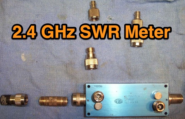 This is a simple 2.4 GHz SWR meter which is based around surplus microwave hardware which can be easily found. The main component is a MECA -20/-20 dB Directional Coupler which has a frequency range of approximately 700 MHz to 2.5 GHz.
 -
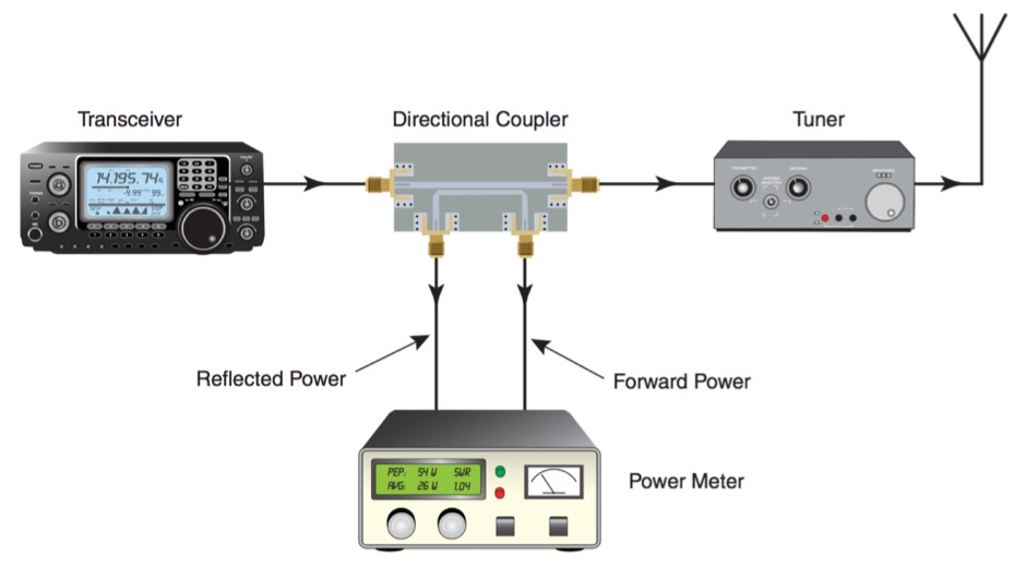
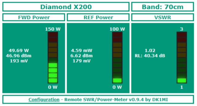 Remotely monitor the output power and SWR of your station via a web browser. WT32/ESP32 based project, combined with a directional coupler setup. It reads two voltages which are supplied by the directional couplers. From these, the respective power is calculated with the help of a calibration data table to be created by the user.
 -
 Online antenna calculator for a basic 3 elements yagi uda directional antenna. The described antenna design offers a front-to-back ratio of at least 20 dB, a gain exceeding 7.3 dBi, and a bandwidth (SWR < 2) of approximately 7% around the center frequency. It has an input impedance of 50 ohms when using a straight split dipole, which can be substituted with a folded dipole of the same length, increasing the impedance to 200 ohms. A matching balun is required for coaxial feeder connection, and the boom should be made of a dielectric material, like wood.
 -
 This project introduces the Loggi, a hybrid antenna merging the wide frequency coverage of log-periodic dipole arrays (LPDA) with the high gain and front-to-back ratio (F/B) of Yagi antennas. Traditional LPDAs span broad frequencies with moderate gain and low VSWR, while Yagis provide high gain and F/B over narrow bands. By analyzing high-Tau LPDA designs, it was found they could nearly match the gain of VHF/UHF Yagis while maintaining excellent patterns, F/B, and front-to-rear ratios (F/R). Optimizing specific elements for target frequencies (e.g., 144.1 MHz) led to the Loggi, which uniquely features all driven elements without passive directors or reflectors. This design effectively functions as a narrowband optimized LPDA, with front elements acting like Yagi directors and rear elements like Yagi reflectors, thus enhancing gain and directional characteristics while retaining broad frequency versatility.
 -
 This page provides detailed information on the 4DX directional wire beam antenna designed by LZ1AQ, LZ1ABC, VK6LW, and DD5LP. It explains how to create this antenna for single or multiple bands using four separate sloping wires. The page includes instructions on achieving directionality, gains, and F/B ratios, as well as generating radiation patterns, VSWR charts, antenna currents diagrams, and Smith charts. It is a valuable resource for hams interested in building and optimizing their own directional wire beam antennas for improved performance and long-distance contacts.
 -
 The document provides a detailed modification guide for the Zetagi HP201 SWR Wattmeter, converting it for HF amateur band usage. It replaces the original circuit with a Tandem Coupler based on the Sontheimer and Frederick directional coupler patent, enhancing accuracy and sensitivity. Key components include Murata toroid cores, scaling resistors, and a new calibration process. Challenges and solutions during the modification process are discussed, ensuring linear results across 160-10m bands. This guide also includes calibration instructions and theoretical insights into the coupler's operation.
 -
 This article presents a novel Top Loaded End-Fed Half-Wave (TLEFHW) antenna design for 20-meter ham radio operation. The antenna features a compact 14-foot vertical radiator with a capacitance hat configuration, eliminating the need for radials or ground systems. Using EZNEC modeling and field testing, the design achieves a 1.5:1 SWR across the 20m band with a 4.11 dBi gain. Key features include quick deployment, lightweight construction, and directional radiation pattern with 110-degree beamwidth. The design, while requiring a 45-foot footprint due to the top hat, offers an effective portable solution for amateur radio operators seeking a no-ground, no-tuner 20m antenna option.
 -
 This page offers a tool for hams to design vertical antennas for portable use on different HF/VHF/UHF bands. Vertical antennas provide omni-directional transmission and reception, making them ideal for DX contacts. By adjusting the antenna's dimensions and viewing radiation patterns and VSWR charts, hams can optimize performance in various terrains. The tool also accounts for the impact of sloping ground on elevation radiation patterns. Perfect for hams looking to enhance their portable radio setups and improve long-distance communication.
 -
 Fully functional weathervane conceals an efficient 2- meter base-station antenna. Your Neighbors and HOA won’t know it’s there and they will love the rooster-vane. The Rooster-Tenna is a covert 2-meter ham radio antenna disguised as a functional weathervane, ensuring seamless integration into residential environments. This improved version features a wide-spaced parallel-fed folded dipole in a compact skeleton slot design. Constructed from aluminum tubing and acrylic supports, it offers omnidirectional, vertically polarized performance suitable for repeater and satellite use. Easy to mount and tune, it achieves a low SWR across the 2m band. With 3D-printable parts available, the Rooster-Tenna blends practicality with stealth, making it an ideal solution for HOA-restricted areas