Search results
Query: air band antenna
Links: 56 | Categories: 0
-
 The Zeppelin antenna, a J-type design, is presented as a two-band HF dipole, offering independent operation on harmonically related frequencies. This resource details its electrical configuration, comprising a half-wave radiator end-fed by a quarter-wave matching section, and explores its historical evolution from early Zeppelin airship applications to modern amateur radio use. The article specifically examines how a Zepp antenna tuned to 28.4 MHz (10 meters) exhibits a harmonic relationship with 15.4 MHz (20 meters), noting a frequency ratio of approximately 1.84:1, which deviates from a perfect 2:1 due to factors like elevation, wire separation, velocity factor, and end-effect. Antenna modeling results, including SWR sweeps at 28.4 MHz (1.1 SWR) and 15.4 MHz (1.6 SWR), are provided through Graph 1 and Graph 2, illustrating the antenna's performance across these bands. Current distribution patterns for both the 28.4 MHz (second harmonic) and 15.4 MHz (first harmonic) operations are visually represented in Figure 2 and Figure 3, respectively. The author also includes a 4NEC2 model's "Symbol Conversion file" definitions and calculated #14 wire dimensions for achieving resonance at 28.4 MHz, with the antenna positioned at a height of 33 feet. The discussion further highlights the antenna's versatility, suggesting its potential as a single-band, center-fed, 15.4 MHz half-wave folded end dipole when fed at a specific low current point. This analysis provides practical insights into constructing and optimizing a multi-band Zepp antenna for HF operations, emphasizing its unique harmonic characteristics and physical compactness.
 -
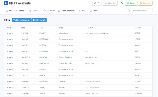 DX web cluster that offers features for both registered and unregistered users. Unregistered users can view spots, filter by band and mode, search for callsigns, while registered users get all that plus the ability to submit spots, upload logs, see DXCC country status, antenna pointing info, real-time maps of spots, email alerts for DXCC countries on-air, and more. Basically, register for free to get the full DX cluster experience.
 -
 Constructing a 4:1 Guanella current balun involves cross-connecting two 1:1 current baluns. At the low-impedance end, transmission lines from each balun are connected in parallel, while at the high-impedance end, they are connected in series. This configuration allows the device to achieve a 1:4 impedance ratio, effectively transforming a 200-ohm load to 50 ohms. The balun described utilizes **FT240-43 toroids** wound with 2.5mm2 twisted pair cable for 8 turns, intended for use with a 20m **Deltaloop antenna**. Measurements performed with a 200-ohm resistor demonstrate satisfactory VSWR and impedance characteristics across the HF bands. The article compares the performance of 2.5mm2 cable versus 1mm enameled wire, recommending the former for superior efficiency. Emphasis is placed on maintaining short core-terminal connections to optimize performance. Additional considerations include the option of integrating a separate Common Mode Choke (CMC) for enhanced common mode current suppression, especially if the balun's inherent suppression is not prioritized.
 -
 The Spartan Sprint Special 40m CW Transceiver, originally documented in 2002 and reproduced in 2019, details a **QRP** direct conversion rig designed for portable operation. This project evolved from an experimental CMOS digital IC receiver, which proved too noisy for weak signals, into a dedicated 40-meter CW transceiver. The author, VE3SMA, aimed for reduced size, lower weight, and decreased receive current drain compared to earlier iterations, drawing on his extensive contesting experience and even his time operating million-watt transmitters at Radio Canada International. This compact transceiver delivers approximately 200 mW output, VFO-tunable over 15 kHz within the 40m band, and weighs a mere 73 grams (0.16 lb) including its balsa wood case. It features fast semi-break-in and sidetone, with a receive current draw of about 14 mA (no signal) and transmit current draw around 125 mA key down. The design incorporates various construction techniques, including knife-cut surface mount boards and through-hole components, often salvaged from junked cordless phones and cellphones. Despite its direct conversion architecture, which offers usable but not superheterodyne-level selectivity, the rig proved effective, achieving a fourth-place finish in a June 2001 Spartan Sprint contest when paired with a 26-foot vertical antenna. The article provides comprehensive circuit details, including an unconventional VFO using a high-speed CMOS inverter chip and a balanced mixer utilizing a 74HC4053.
 -
 The XW4DX DXpedition website documents the amateur radio operation from Laos, a country ranked #98 on Clublog's Most Wanted list. This resource provides insights into the planning and execution of a significant DXpedition, including antenna choices like _Hexbeams_ at 14m, a 4-square for 40m, and a top-loaded vertical for 160m. The team, comprising operators such as _F4BKV Vincent_ and _F2DX Patrick_, focused on challenging paths, particularly towards the North American East Coast, where Laos is #41 most wanted. Operational constraints included prohibitions on 6m, 30m, 60m, and 80m bands within Laos, necessitating a focus on other HF frequencies, especially 160m and 40m. The expedition utilized up to five stations simultaneously, with equipment transportation being a major logistical challenge, partially mitigated by direct shipments from _Spiderbeam_ and donor support. The expedition ran from November 16th to 27th, 2023, with the complete XW4DX log uploaded to LoTW by December 23rd, 2023. This site serves as a historical record of their efforts to put Laos on the air for DXers worldwide.
 -
 TX5EU 2026 DXpedition to Raivavae Island, **OC-114**, within the Austral Islands, providing a detailed account of the German/Dutch team's operations. The resource outlines the participation of operators such as DL2AWG Guenter, PA2KW Evert, and DK2AMM Ernoe, who engaged in CW, SSB, RTTY, and various digital modes. It documents the real-world challenges encountered, including significant equipment failures and antenna damage to 80/60m, 30m, and 10m verticals due to adverse storm conditions. The page offers timely news updates on the expedition's progress, noting repairs to a power amplifier's 10/12m bandpass filter, which enabled three stations to utilize amplification. Earlier reports highlighted power failures and the loss of multiple power amplifiers, necessitating one station to operate barefoot FT-8 with 100W. The team's persistent efforts to repair antennas as weather permits are also detailed, reflecting the dynamic nature of remote island operations.