Search results
Query: 137 khz
Links: 10 | Categories: 0
-
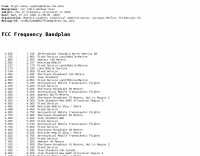 This resource presents the _FCC_ Online Table of Frequency Allocations, codified under 47 C.F.R. § 2.106. The document details frequency assignments across the electromagnetic spectrum, from 0 kHz to beyond 2170 MHz, specifying allocations for various radio services including amateur, maritime mobile, aeronautical radionavigation, and broadcasting. The table is structured with columns for International Table (ITU Radio Regulations Article 5, Section IV, 2019 Edition), United States Table (Federal and Non-Federal), and corresponding _FCC_ Rule Part(s). Specific frequency ranges, such as **135.7-137.8 kHz** and **472-479 kHz**, are identified with their primary and secondary allocations, including Amateur Radio (Part 97) and Maritime Mobile (Part 80). The methodology involves direct publication of regulatory data, reflecting amendments adopted by the _FCC_ that may not yet be codified in the Code of Federal Regulations. Each entry provides the allocated service (e.g., METEOROLOGICAL AIDS, RADIONAVIGATION), relevant footnotes (e.g., 5.53, US18), and the applicable _FCC_ Rule Part. For example, the 1800-2000 kHz range is allocated to AMATEUR radio under Part 97, alongside MOBILE services. Contact information for the Office of Engineering and Technology Policy and Rules Division is provided for inquiries regarding the data. DXZone Focus: Regulatory Database | FCC Publication | Frequency Allocation | Rule Part Reference
 -
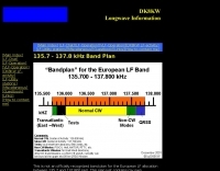 The 2.1 kHz wide European LF allocation between 135.7 and 137.8 kHz is detailed in this observed band plan, offering guidance for activity within this narrow segment. It specifically addresses the challenge of locating weak signals, such as those from Slow-CW stations, which can have bandwidths of only a few Hertz. The resource emphasizes the utility of precise frequency knowledge when operating with narrow DSP filters, like a 30 Hz filter for CW, to differentiate multiple stations within a very small band segment. The plan, though not officially recognized, provides practical orientation for operators, particularly those new to the _LF band_. It references a similar plan published by the _RSGB_ in the January 2000 issue of _RADCOM_, suggesting a community-driven approach to band organization. The content highlights the importance of spectral awareness, noting that multiple stations can occupy minimal bandwidth, a concept illustrated by spectrographic analysis.
 -
 Operating on the 2200m band (135.7-137.8 kHz) often presents challenges for amateur radio transceivers, which typically exhibit poor receiver performance at these very low frequencies. This project addresses the issue by providing a design for a dedicated 137 kHz antenna preamplifier, specifically tailored to improve signal reception for radios such as the _Yaesu FT-817_. The preamplifier circuit utilizes a low-noise FET input stage, crucial for minimizing self-generated noise and maximizing the signal-to-noise ratio from weak LF signals. The design includes a detailed schematic, component values, and construction notes, enabling homebrewers to build a functional unit. The goal is to achieve significant gain, making the faint signals on 2200m more discernible and improving overall band usability. Key design considerations include impedance matching to typical antenna systems and ensuring stable operation across the narrow LF segment. The circuit aims for a **low noise figure** and sufficient amplification to overcome the inherent limitations of general-purpose HF transceivers when operating below **200 kHz**.
 -
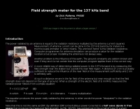 Field strength meter for the 137 kHz band by PA0SE
 -
 137.7 kHz QRSS beacon exciter is described, utilizing a single chip for operation on the 2200m amateur band. The design focuses on simplicity and efficiency for weak signal applications, providing a compact solution for generating QRSS signals. This project targets the DX portion of the band, enabling long-distance communication with minimal power output. The resource details the construction and functionality of the **QRSS beacon**, emphasizing its **low-power operation** and suitability for experimental amateur radio. It provides insights into the circuit's architecture and potential for integration into existing station setups. The design aims to offer a practical and accessible entry point for amateurs interested in weak signal modes on the LF/MF bands.
 -
 137 kHz propagation analysis details ground wave and sky wave mechanisms, drawing heavily from **CCIR Rec. 368-6** for ground wave field strength predictions and **CCIR Rep. 265-7** for sky wave modeling. The resource presents field strength values for 1 W ERP at varying distances, considering ground conductivity and permittivity for ground wave, and ionospheric height (70km daytime, 90km nighttime) for sky wave. Key factors like ionospheric focusing (factor "D"), reflection coefficient ("RC"), and antenna ground pattern factors ("Ft", "Fr") are quantified for 137 kHz, enabling calculation of sky wave field strength. Practical coverage ranges are derived for 137 kHz, showing useful ground wave coverage up to 1600 km over seawater and 1100 km over average ground, assuming a -9 dBuV/m noise floor. Sky wave coverage extends beyond 2200 km during night-time and winter daytime, but is negligible during summer daytime at solar minimum. The document also compares ground wave and sky wave strengths, identifying crossover distances at 550 km (night-time), 750 km (winter daytime), and 1250 km (summer daytime), where interference fading can occur. Adjustments for solar maximum conditions are provided, indicating 2-11 dB higher sky wave values depending on distance and season.
 -
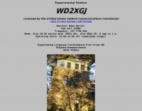 Experimental Longwave Transmissions from Tower Hill wayland Massachusetts Operator Name Warren, Ham Call K2ORS, Frequency: 137.7796 KHz
 -
 The 2200-meter band (135.7-137.8 kHz) presents unique challenges for amateur radio operators due to its narrow 2.1 kHz bandwidth, low signal levels, and high noise. W1TAG explores various transmission modes suited for this demanding environment, highlighting that traditional voice modes like SSB and AM are impractical. Plain old CW serves as the baseline, demonstrating effectiveness across different modes, though signal-to-noise ratio (SNR) significantly limits practical speeds. The article notes that reducing CW speed below 5 WPM can improve copy, especially with computer-aided spectrum analysis software capable of decoding signals too weak for human ear reception. QRSS, or "CW sent slowly enough that speeds are best expressed in seconds per dot," is a key mode for LF work, with examples ranging from 3 seconds/dot to extreme 240 seconds/dot transmissions. _Argo_ by I2PHD is mentioned as a simple program for QRSS, enabling reception of signals like BRO, a Part 15 beacon, at a distance of **1100 miles**. Other modes discussed include Dual Frequency CW (DFCW), which uses frequency shifts to distinguish dots and dashes, and Binary Phase Shift Keying (BPSK), a phase modulation technique employing 0 to 180-degree phase flips. WOLF (Weak-signal Operation on Low Frequency), a specialized BPSK form by KK7KA, encodes 15-character messages into 960-bit packages, taking 96 seconds to transmit, and has demonstrated successful reception over **672 seconds** for a message from a 1-watt beacon. Further modes include PSK, FSK variations like JASON and MSK, and graphical modes such as Hellschreiber and Chirped Hell. The article concludes with a practical chart comparing the time required to send a simple message like "WD2XES FN42CH " across these diverse LF modes, offering valuable insights for operators planning contacts on the low bands.
 -
 WD2XSH Experimental Station (505 - 510 KHz) WD2XKO Transmitting Station Stanfield,NC operating between 135.7 to 137.8 KHz.
 -
 DF0WD/DL4YHF's Longwave Overview details amateur radio operations on the 135.7 to 137.8 kHz segment in Germany. The author outlines the "inofficial" European band plan, specifying segments for QRSS, TX tests, beacons, conventional CW, and data modes. Early LF activities at DF0WD began with a 20-watt CW transmitter, later upgraded to a homemade linear transverter capable of 100 watts, driven by an Icom IC706 on 10.137 MHz. The station's antenna system includes a 200-meter wire, approximately 10 meters above ground, supported by football field light-masts. Despite its length, the antenna's efficiency is noted as very low due to the immense wavelength of about 2.2 km. The author's experience highlights the significant challenge of achieving effective radiated power (EIRP) on LF, estimating DF0WD's EIRP at around 80 milliwatts based on field strength measurements from PA0SE. DF0WD/DL4YHF has successfully worked numerous countries on 136 kHz CW, including DL, F, G, GI, GM, GU, GW, HB9, HB0, LX, OE, OH, OK, OM, ON, OZ, PA, and SM. The author also mentions ongoing efforts to log contacts with CT, EI, LA/LG, and to complete a two-way QSO with Italy, demonstrating persistent activity on this challenging band.