Search results
Query: 17m Moxon
Links: 8 | Categories: 1
Categories
-
 Constructing a **reduced-size coaxial Moxon rectangle** antenna for the 17-meter band is detailed, presenting a method to achieve a compact directional antenna. The resource outlines the use of RG-58/U coaxial cable for elements, enabling a substantial reduction in physical dimensions compared to traditional wire or tubing Moxon designs. It provides specific instructions for tuning coaxial elements using an **MFJ-259B antenna analyzer**, including a formula to calculate trimming lengths based on measured resonance and desired frequency. The article explains how to prepare the coaxial cable for both driven and reflector elements, specifying connections for testing and final assembly. Performance data from an MFJ-259B shows SWR readings between 1.0 and 1.2 across 18.068 MHz to 18.168 MHz, with R values from 51 to 59 ohms and X values of 0 or 6 ohms. The antenna's power handling is approximately 500 watts continuous, limited by the RG-58/U coax. Comparative receive testing against an All-Band Sterba Curtain at 50 feet indicated a 2 S-unit reduction for the coaxial Moxon at 9 feet, suggesting optimal performance at a height of 34-40 feet for a 15-18 degree take-off angle. The design achieves an electrical quarter wavelength with over 30 percent size reduction.
 -
-
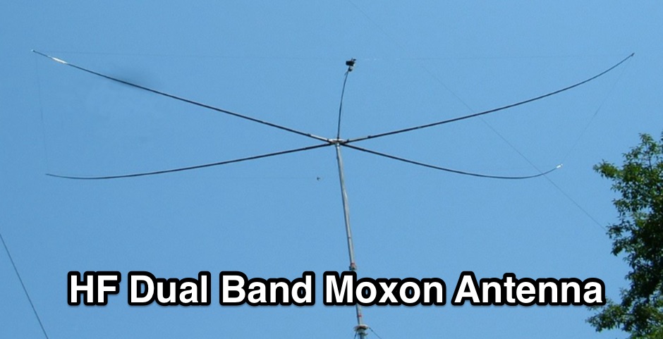
 Operating on the 12-meter and 17-meter WARC bands often benefits from directional antennas that offer gain and front-to-back ratio in a compact footprint. This resource details the construction of a dual-band wire beam, specifically a _Moxon Rectangle_ design, for these two bands. It outlines the use of fiberglass tubing for spreaders, _Flexweave_ wire for the elements, and an aluminum hub with die-cast flanges to create a robust structure. The design allows for a single 50-ohm feed point, simplifying station setup and minimizing feedline loss. The project provides specific dimensions and material choices, enabling a homebrewer to replicate the antenna. While inspired by L.B. Cebik's (W4RNL) theoretical work, this implementation focuses on practical construction techniques for a physical build. The resulting antenna offers directional characteristics suitable for DXing and contesting on 12m and 17m, providing an alternative to full-sized Yagis or compromise verticals, particularly for those with limited space.
 -
 This technical note explores the application of **Moxon rectangle** antennas for WARC bands, specifically 17 and 12 meters, as compact directional alternatives to standard Yagis. It details three design approaches: a dual-band Moxon using open-sleeve coupling, a Moxon-Yagi combination, and a simplified 1.5 Moxon rectangle. The document provides specific dimensions in feet for aluminum tubing elements (0.75" and 0.5" diameter) for each configuration, along with projected free-space gain, front-to-back ratio, and feedpoint impedance (R+/-jX Ohms) across the respective band segments. Performance tables illustrate gain (dBi), front-to-back ratio (dB), and 50-Ohm VSWR for each design. The dual-band Moxon, despite its compact 7-foot boom, is not recommended due to extreme sensitivity to construction variations, leading to rapidly changing performance characteristics. The Moxon-Yagi combination, featuring a 17-meter Moxon and a 12-meter director-driver Yagi, is presented as a more practical and adjustable solution, offering stable performance with a 10-foot boom. NEC model descriptions are included for simulation in programs like EZNEC, NEC-Win Plus, AO, or NEC4WIN.
 -
 Details the construction of a **17-meter Moxon Rectangle** antenna, specifically engineered for mounting on a mast beneath an existing beam. The design incorporates insulated wire calculations (0.95804 x generator length) to compensate for velocity factor differences, utilizing readily available materials such as crappie poles for elements, PVC for the boom and mast, and a Budwig HQ-1 dipole connector for the 50 Ohm coax feed. The project outlines a step-by-step assembly process, including mast construction from PVC T-connectors and pipe, element fabrication from crappie poles, and securing elements to prevent droop. Initial testing demonstrated an SWR of 1.3:1 on 17 meters, achieving a 5-8 signal report into Texas with 100 watts. Subsequent reinforcement and elevation of the antenna resulted in a 15 over 9 report from Florida. Comparative testing against an 88-foot center-fed Zepp antenna indicated superior performance, with the Moxon consistently outperforming the Zepp and receiving signals the Zepp could not. A notable DX contact with JA8NFV in Hokkaido, Japan, yielded a 5-9+ signal report both ways using 100 watts.
 -
 The AE6AC 17-meter Moxon antenna project details the construction of a wire beam using readily available materials. This design utilizes four 16-foot fiberglass crappie poles for support, joined at the center with 3/4-inch Schedule 40 PVC pipe and "T" slip fittings. Wire segment lengths for 18.135 MHz were calculated using _Moxgen_ software by AC6LA, with specific dimensions provided in feet and inches for precise cutting. Key construction decisions include joining the crappie pole bases into a central hub and attaching the 16-gauge silver-plated copper wire to the pole ends. Dacron cord with a fisherman's knot secures the wire to the pole tips, while small wire loops at the corners maintain antenna shape. Plexiglas pieces serve as insulators for sections "A" and "C." The finished antenna, weighing less than 10 pounds, mounts on a fiberglass windsurfer mast and incorporates a 1:1 current mode ferrite bead balun. Performance measurements with an _MFJ-259B_ show an SWR better than 1.5:1 across the 17m band, with good front-to-back ratio and reported signal strength improvements of 2-4 S-units over vertical dipoles. Initial contacts included VK2AXB, ZF6GS, and KL1M.
 -
 Presents construction details for Moxon antennas, specifically focusing on 10-meter and 17-meter band configurations. It covers practical aspects of building these directional wire arrays, including element spacing, feedpoint considerations, and material choices for optimal performance. The resource emphasizes homebrewing techniques suitable for amateur radio operators. Discusses the advantages of the Moxon rectangle design, such as its compact footprint compared to a full-size Yagi and its favorable front-to-back ratio. It provides insights into achieving proper impedance matching and structural integrity for portable or fixed installations. The content includes photographic examples of constructed antennas. Explains the iterative process of tuning and optimizing Moxon antennas for specific frequency segments within the 10m and 17m bands. It offers guidance on minimizing SWR and maximizing gain, drawing from real-world building experiences to assist constructors in replicating successful designs.
 -
 Constructing a compact directional antenna for the 17-meter band, this resource details the build process for a Moxon rectangle, a two-element Yagi variant with folded-back elements. It covers the antenna's evolution from the _VK2ABQ beam_ and provides specific dimensions for a version built using fishing pole whips. The content includes a discussion of the antenna's radiation pattern, feedpoint impedance, and its inherent front-to-back ratio, which is often superior to a standard two-element Yagi. Practical considerations for element spacing and material choices are also addressed, alongside a visual representation of the antenna's physical layout. Performance data presented includes a comparison showing the Moxon rectangle's **2.5 dB gain** over a half-wave dipole and a front-to-back ratio of **20 dB**. The resource also touches upon the antenna's relatively wide bandwidth for a two-element beam and its suitability for portable operations due to its compact footprint. It offers insights into optimizing the design for specific operating conditions and discusses the advantages of its lower take-off angle compared to omnidirectional wire antennas, making it effective for DX contacts on the 17-meter band.