Search results
Query: 70 mhz amplifier
Links: 14 | Categories: 0
-
 A 144 MHz kilowatt amplifier project details the construction and performance of a high-power VHF linear using the GU74b tetrode. This Russian tube, equivalent to the Svetlana 4CX800, is noted for its conservative datasheet ratings, performing closer to 800-1000W anode dissipation in practical applications. The design prioritizes compactness and achieves 1.2 kW output with only 20W of drive power, demonstrating a 70% efficiency at 2.5 kV plate voltage. The amplifier has been successfully deployed in demanding _EME_ (Earth-Moon-Earth) operations since June 1994. Challenges encountered during development included achieving stability with a grid-1 input configuration. The author, _CT1DMK_, opted not to publish the full design due to its complexity, suggesting it might be difficult for less experienced builders to replicate successfully. However, he invites direct contact for those with specific interest in the design. Future plans include a "144MHz GS35b compact amplifier" project, promising another kilowatt-plus design. This resource offers insights into high-power VHF amplifier construction and the practical application of specific power tubes.
 -
 Demonstrates the construction of a **homebrew spectrum analyzer** designed by Wes Hayward, W7ZOI, and Terry White, K7TAU, enabling radio amateurs to build a capable test instrument without significant expense. The resource details a _double-conversion superheterodyne_ circuit, employing intermediate frequencies of 110 MHz and 10 MHz, and covers essential blocks such as the time base, logarithmic amplifier, resolution filters, and local oscillators. It highlights the use of hybrid and monolithic ICs, including mixers, amplifiers, and VCOs, to simplify construction while maintaining performance. The design supports useful measurements in the 50 kHz to 70 MHz range, with methods outlined for extending capabilities into VHF and UHF. The authors emphasize that this analyzer, while simple to build, is intended for serious measurements, requiring careful control of signal levels to avoid spurious responses. It uses an oscilloscope for display, with specific instructions for calibration and adjustment of various stages, including the log amplifier and IF gain. The guide provides detailed schematics and component lists for each section, such as the 110 MHz triple-tuned band-pass filter, which achieved **90 dB** image rejection, a significant improvement over double-tuned circuits. Practical advice on alignment and troubleshooting is included, drawing on the authors' extensive experience in RF circuit design.
 -
 This resource details the computer-optimized design of the _ZS6BKW_ multiband dipole, an evolution of the classic _G5RV_ antenna. It begins by referencing the original 1958 RSGB Bulletin article by Louis Varney G5RV, explaining the operational principles of the G5RV's flat-top and open-wire feedline on 20m and 40m, noting its impedance transformation characteristics for valve amplifiers of that era. The article then transitions to the rationale for optimizing the design for contemporary solid-state transceivers requiring a 50 Ohm match. The core of the project involves using computer modeling to determine optimal lengths for the flat-top and matching section, aiming for a VSWR of less than 2:1 on multiple HF bands. It discusses the process of calculating feedpoint impedance based on antenna length and frequency, referencing professional literature from Professor R.W.P. King at Harvard University. The analysis also considers the characteristic impedance (Z(O)) of the open-wire line, identifying a broad peak of adequate values between 275 and 400 Ohms. Specific design parameters for the improved ZS6BKW are presented, including a shorter flat-top and a longer matching section compared to the original G5RV, with a velocity factor of 0.85 for the 300 Ohm tape. The article confirms acceptable matches on 7, 14, 18, 24, and 28 MHz bands when erected horizontally at 13m, and also discusses performance in an inverted-V configuration, noting frequency shifts. The author, Brian Austin ZS6BKW, emphasizes the antenna's suitability for modern 50 Ohm coaxial cable without a balun.
 -
 This document details the design and construction of the PA70H, a 50-watt RF amplifier for the 70MHz (4-meter) amateur radio band. Built around the Mitsubishi RD70HVF1 MOSFET transistor, the amplifier delivers 45-55W output with 3-5W input power while operating on 13.8V DC at approximately 7-8A. The PCB design incorporates multiple protection circuits including overcurrent, SWR, and temperature control. The amplifier features various control modes including GND PTT, +13.8V PTT, and RF VOX. Two versions are available: PA70HLI (requiring 100mW input with additional driver) and PA70H (for 3-5W input). The comprehensive documentation includes circuit diagrams, assembly instructions, and performance data showing successful operation from both 100mW and 3.5W input sources.
 -
 Linear Amp UK specializes in the design and production of high-quality linear amplifiers, offering models for HF, VHF, and UHF amateur and commercial applications. The company emphasizes nearly 30 years of experience in crafting each unit, ensuring robust performance and longevity. Their product line includes amplifiers engineered for a 100% duty cycle, promoting continuous and reliable operation across various modes. The amplifiers feature solid, dependable designs, ensuring quiet and effortless performance during transmission. Each unit is hand-built to stringent standards, reflecting a commitment to durability and operational stability. All products are CE approved, confirming compliance with European safety and environmental directives, and come with a standard two-year warranty, providing assurance to operators. Key specifications often include coverage for 1.8-30MHz (WARC bands), 50MHz, 70MHz, and 144MHz, utilizing tubes such as 811, 572, 811A, 572B, GS35, GS35B, 8877, 3CX1500, and _3CX1500A7_ in their designs.
 -
 A 160W linear amplifier for 4 meters band based on GI0GDP
 -
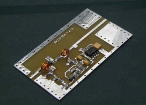 The prototype for this amplifier was originally designed for 70cm and was used on the 2004 3B9C Dx-pedition to Rodriguez Island for satellite and EME. It had a noise figure of 0.49dB with an associated gain of 20dB.
 -
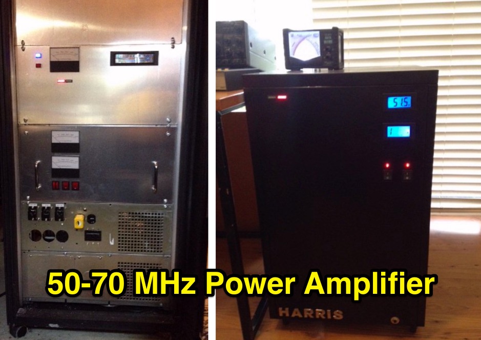 Harris Platinum I Solid State Channel 2, and 3 TV Amplifier Modules for use, on 50 or 70 MHz
 -
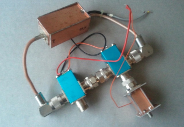 A ham radio home made preamplifier for 50 MHz and 70 MHz bands
 -
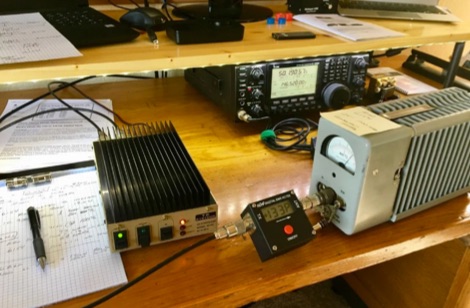 TE Systems 0510G 50 MHz meter amplifier set up for 10 watts in and 170 watts out.
 -
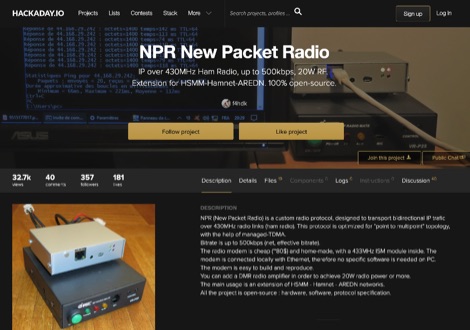 NPR (New Packet Radio) is a custom amateur radio digital protocol, designed by F4HDK to transport bidirectional IP trafic over radio links on the 70cm band. This IP protocol is optimized for point-to-multipoint topology, with the help of managed-TDMA. Bitrate is up to 500kbps. Home Made modem has a built-in ethernet port to connect to PC. To boost power a DMR amplifier is required to reach 20W. This project is an extension of HSMM - Hamnet - AREDN networks
 -
 This PA has been designed by Sergey EX8MLE and uses three Mitsubishi RD100HHF1 FETs, Frequency Range 70 to 72 MHz
 -
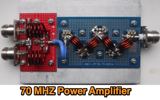
 This is a power amplifier project for a RF 600W 1.8 MHz to 70 MHz linear amplifier including a Low Pass Filter. Projects includes schematics, pictures, PCD design, fans details, note on PA ferrite chokes and assembling instructions
 -
 Manufacturer of 50MHz, 70MHz, 144MHz, 222MHz, 432MHz, 900MHz or 1.2GHz transverters and VHF UHF amplifiers