Search results
Query: VOX circuit
Links: 4 | Categories: 0
-
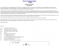 Demonstrates building a basic _VOX circuit_ to add voice-operated transmit functionality to HF transceivers that lack this feature. The design utilizes a _1458 dual op-amp_ (two 741 op-amps in one package) to amplify microphone audio and act as a comparator, driving an NPN switching transistor for PTT control. A capacitor, C2, provides the necessary delay before unkeying the PTT, with a variable resistor, R6, allowing adjustment of the VOX level for specific microphones or voices. This low-cost circuit, detailed with a full parts list, offers a practical solution for hams seeking to enhance their budget HF rigs. The author, N1HFX, provides guidance on initial setup, including advice on microphone gain and the use of headphones to prevent speaker audio from re-keying the transceiver. Modifications for adjusting delay time are also included, suggesting increasing R8 to 10K for more delay or decreasing C2 to 22µF for less.
 -
 A circuit which had been used in many other application before. The configuration described here is optimized for IPHONE/radio operation.
 -
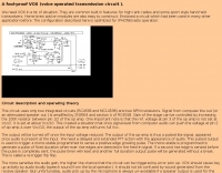
 This document details the design and construction of the PA70H, a 50-watt RF amplifier for the 70MHz (4-meter) amateur radio band. Built around the Mitsubishi RD70HVF1 MOSFET transistor, the amplifier delivers 45-55W output with 3-5W input power while operating on 13.8V DC at approximately 7-8A. The PCB design incorporates multiple protection circuits including overcurrent, SWR, and temperature control. The amplifier features various control modes including GND PTT, +13.8V PTT, and RF VOX. Two versions are available: PA70HLI (requiring 100mW input with additional driver) and PA70H (for 3-5W input). The comprehensive documentation includes circuit diagrams, assembly instructions, and performance data showing successful operation from both 100mW and 3.5W input sources.
 -
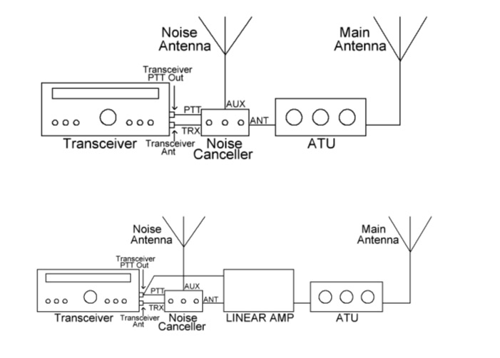 Noise Canceller kit originally developed about 1989 by G4WMX and GW3DIX and improved by DK9NL and DG0KW.The VK5TM Noise Canceller is another version of the design, with the HF Vox circuit removed and a couple of other minor changes, including the use of SMD JFETs and a double-sided pcb.