Search results
Query: circuits diagrams
Links: 4 | Categories: 0
-
 This resource, "Transistor Audio Preamplifier Circuits," offers comprehensive design guidelines for constructing **bipolar transistor** audio preamplifiers. It delves into critical aspects such as quiescent current setting, voltage gain calculation, and the impact of various component choices on circuit performance. The content provides several _schematic diagrams_ illustrating different preamplifier configurations, including single-stage common emitter and two-stage designs, alongside explanations of their operational characteristics and practical implementation considerations. The analysis extends to frequency response, noise performance, and distortion, providing insights into optimizing these parameters for specific audio applications. The resource presents calculated gain figures for various stages, demonstrating how to achieve desired amplification levels. It also discusses the importance of proper power supply decoupling and input/output impedance matching, crucial for integrating these preamplifiers into larger audio systems or ham radio transceivers. The practical application of these designs is evident in their suitability for microphone preamplifiers or general-purpose audio amplification.
 -
 This document details the design and construction of the PA70H, a 50-watt RF amplifier for the 70MHz (4-meter) amateur radio band. Built around the Mitsubishi RD70HVF1 MOSFET transistor, the amplifier delivers 45-55W output with 3-5W input power while operating on 13.8V DC at approximately 7-8A. The PCB design incorporates multiple protection circuits including overcurrent, SWR, and temperature control. The amplifier features various control modes including GND PTT, +13.8V PTT, and RF VOX. Two versions are available: PA70HLI (requiring 100mW input with additional driver) and PA70H (for 3-5W input). The comprehensive documentation includes circuit diagrams, assembly instructions, and performance data showing successful operation from both 100mW and 3.5W input sources.
 -
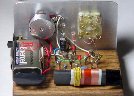 Collection of several Crystal Radio receiver circuits with schematics diagrams and pictures
 -
 Station QRP presents various **circuit diagrams** for constructing low-power AM vacuum tube shortwave transmitters, catering to enthusiasts interested in vintage radio technology. The resource details schematics ranging from simple to more complex designs, enabling hams to build their own QRP AM transmitters for operation on frequencies like 6.925 kHz AM. It emphasizes the use of vacuum tubes, providing a technical foundation for understanding and replicating classic shortwave broadcasting methods. The content is geared towards those who enjoy the hands-on aspect of electronics and the unique characteristics of tube-based RF circuits. Building these transmitters allows operators to experience the nostalgia of early shortwave radio, with the site specifically mentioning a pioneer station on 6.925 kHz AM. The designs facilitate experimentation with low-power AM transmission, offering practical application for homebrew projects. The focus on QRP (low power) operation aligns with a segment of the amateur radio community that values efficiency and minimalist setups, providing a distinct alternative to modern solid-state transceivers.