Search results
Query: handheld radio receiver
Links: 4 | Categories: 0
-
 The Yaesu VX-5R, manufactured between 199x and 200x, offers a transmit frequency range covering 50-52 MHz, 144-146 MHz, and 430-440 MHz for European models, with US versions extending to 50-54 MHz, 144-148 MHz, and 430-450 MHz. Its receiver boasts an impressive wideband capability from 0.5 MHz to 999 MHz, with cellular frequencies blocked in some regions. The unit provides up to 5 watts RF output on 6 meters and 2 meters, and 4.5 watts on 70 centimeters, with selectable lower power settings down to 300 mW. This handheld transceiver utilizes a double conversion superheterodyne receiver system, featuring a 47.25 MHz first IF for FM and 45.8 MHz for WFM. Key specifications include a frequency stability of ±5 ppm across a wide temperature range and a current drain of 25-150 mA on receive. The VX-5R supports 220 regular memory channels with alpha tags, 3 home channels, and 10 NOAA weather channels, all stored in non-volatile EEPROM. Additional features include CTCSS/PL and DCS with tone search, ARS, ARTS, an internal voltmeter, and a Spectra-Scope. The device operates on a 7.2 VDC battery pack or 10-16 VDC external power, weighing 255 grams with dimensions of 58x88x27 mm. The VX-5R was also available as the metallic silver VX-5RS.
 -
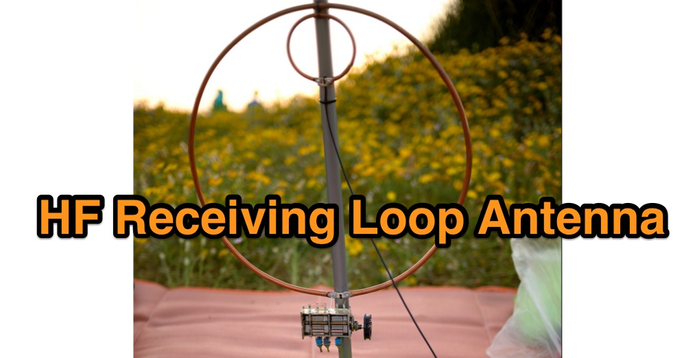 The antenna was built to be used for shortwave listening with a Tecsun PL-660 radio receiver. Later it was used with Yaesu VX-6 handheld transceiver and with Yaesu FT-817ND for shortwave listening.
 -
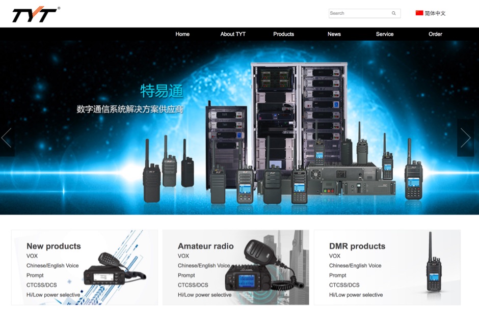 TYT Electronics boasts of 15-year experience in two-way radio manufacture. Produce DMR transceivers, handhelds, receivers and mobile radios, analog amateur radio and commercial VHF transceivers
 -
 The 222 MHz Transverter project, based on Zack Lau's (W1VT) original July 1993 QEX magazine design, provides an IF of 28 MHz for both transmit and receive paths. Rick Bandla (VE3CVG) contributed supplemental notes and construction details, including modifications to achieve 10 mW output power from an initial 4 mW PEP. The design incorporates three distinct boards: a Local Oscillator (LO), a Transmitter (Tx), and a Receiver (Rx), with an estimated parts cost of just over $150 CDN, significantly less than commercial kits. Construction involves both through-hole and surface-mount components, with specific guidance on mounting MAV and MAR devices, grounding techniques, and component selection. The project details include parts lists, schematics for the LO, Tx, and Rx, and board layouts. Troubleshooting advice emphasizes sequential testing, starting with the LO, then Tx, and finally Rx, using a 194 MHz and 222.100 MHz capable FM handheld for signal tracing. Further enhancements are discussed, such as an optional Tx driver stage to boost output to 100 mW and the potential modification of a Motorola Maxor 80 PA for 222 MHz SSB/CW operation. The resource also covers practical aspects like power attenuation pads for IF radios (e.g., FT817) and considerations for enclosure design, including repurposing a Maxor 80 case. Performance reports indicate successful 70 km contacts with only 4 mW output.