Search results
Query: schematics
Links: 90 | Categories: 71
Categories
- Antique Radios > Schematics
- Antennas > Baluns > 1 to 1 Balun
- Antennas > 20M > 20 meter Vertical Antennas
- Antennas > Baluns > 4 to 1 balun
- Operating Modes > Amateur Television
- Technical Reference > Amplifiers
- Technical Reference > Antenna Rotator
- Technical Reference > Antenna Switch
- Technical Reference > APRS
- Technical Reference > Attenuators
- Technical Reference > ATV
- Technical Reference > Audio
- Technical Reference > Beacon keyers
- Radio Equipment > HF Vertical Antenna > Butternut HF2V
- Antennas > Capacitive
- Technical Reference > Components
- Technical Reference > Receivers > Crystal radio
- Technical Reference > Digital ATV projects
- Radio Equipment > Receivers > Drake R-4B
- Technical Reference > DTMF
- Technical Reference > Dummy Loads
- Technical Reference > Duplexers
- Antennas > EH
- Antennas > End-Fed > End Fed Half Wave Antenna
- Technical Reference > Frequency Counter
- Antennas > HB9CV
- Technical Reference > Headsets and Speakers
- Technical Reference > HF Radios
- Technical Reference > Homebrew
- Antennas > Horn
-
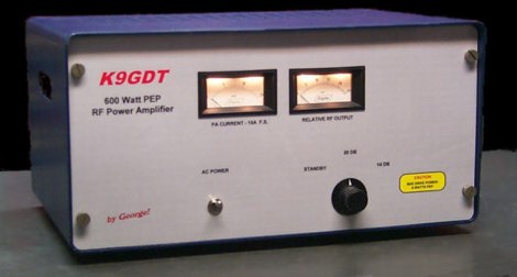 Schematics plans by K9GDT and all infos to build a 600 Watt HF Amplifier. The amplifier uses four Motorola MRF150 50 volt TMOS power FETs configured in push-pull/parallel and biased for class AB linear operation.
 -
 Galaxy web site updates and additions with modifications, diagrams, and schematics for galaxy radios
 -
 The project details a DIY SWR/Wattmeter designed around an _Arduino Uno_ shield, providing capabilities to measure RF power from 2 to **200 watts** and Standing Wave Ratio (SWR) for HF amateur radio bands. This construction features a compact design, integrating the measurement circuitry directly onto a custom PCB that interfaces with the Arduino Uno microcontroller. Key components include a directional coupler for sensing forward and reflected power, precision rectifiers, and analog-to-digital conversion for processing RF signals. The Arduino firmware handles calibration, calculations, and displays the results on an integrated LCD, offering real-time feedback on antenna system performance. The design prioritizes simplicity for homebrewers. Performance specifications indicate accurate readings within the **2-200W** power range, suitable for typical QRP to medium-power HF operations. The project provides schematics and a basic overview of the software logic.
 -
 Detailed plans of my homebrew receiver. Frequency coverage is from below 300kHz to 30MHz. Pictures, schematics, board layouts, parts lists and more can be found here.
 -
 Roy G4WPW has collected one of the most complete and interesting pages for microphone connections schemas and wiring. Includes Kenwood microphones schematics as well as Yaesu Icom Alinco Adonis Drake Heil JRC MFJ schematics
 -
 K9AY loop antenna installed at PA6Z Contest group. This is a receiving antennas for the low bands (160m, 80m and 40m). Include schematics and info on a building the control box, preamplifier and low-pass filter
 -
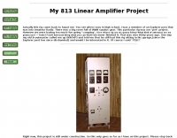 813 Linear Amplifier Project includes many schematics, drawind and assembling construction
 -
 Specializes in antique radio schematics, circuit diagrams and service data for vintage tube radios. Carries information for American, Canadian and European antique radios.
 -
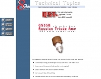 50 MHz 1500 Watt Russian GS35B amplifier. Well documented. Complete construction details,pictures,schematics, and more.
 -
 Service information, modifications, diagrams, manuals and schematics, and technical files on Galaxy DX Radios.
 -
-
 Dealer for Cb radios, Cb antenna & accessories Galaxy radio, Cobra cb radio, Ranger, Texas Star, Palomar. Police scanner, radar detector, GPS, GMRS, FRS, Wilson cellular amplifier & antennas. Owners manuals, schematics and links.
 -
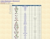 Service information, manuals, diagrams pictures and schematics, and technical files on Cobra Radios
 -
 Contain schematic diagram of many different radio, and some operations instructions.
 -
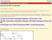 Complete 144/50 MHz transverter with GaAs Fet LNA and 400 mW out. No printed circuit board. Schematics and images by Christoph Petermann DF9CY
 -
 WV7U YC156 and 3CPX800 amplifier projects. See pictures, schematics, test data, links, and more!
 -
 Based on Motorola MRF454, schematics and component list
 -
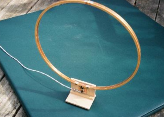 Schematics, mechanical drawings and picture of a Receiving loop antenna by N5ESE - N5FC
 -
 Electronics service manual exchange, IC-706 service parts, schematics from ICOM official manual
 -
 Service Manuals & Schematics, supplied for most types of equipment, Audio, TV, Video, Test and Ham Radio
 -
 Simple eprom programmer for 27Cxx family , used in TNC and G3ruh modem, eprom tutorial, schematics and KissEprom software for windows by iz7ath
 -
 Schematics and plans to build a custom CAT and audio pc interface
 -
 Infomration schematics and pictures about various hf and vhf QRO linear amplifiers
 -
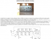 Italian page including pictures schematics diagrams of an home made linear amplifier using four EL509 in parallel. Output power is about 700W.
 -
 Demonstrates the construction of a **homebrew spectrum analyzer** designed by Wes Hayward, W7ZOI, and Terry White, K7TAU, enabling radio amateurs to build a capable test instrument without significant expense. The resource details a _double-conversion superheterodyne_ circuit, employing intermediate frequencies of 110 MHz and 10 MHz, and covers essential blocks such as the time base, logarithmic amplifier, resolution filters, and local oscillators. It highlights the use of hybrid and monolithic ICs, including mixers, amplifiers, and VCOs, to simplify construction while maintaining performance. The design supports useful measurements in the 50 kHz to 70 MHz range, with methods outlined for extending capabilities into VHF and UHF. The authors emphasize that this analyzer, while simple to build, is intended for serious measurements, requiring careful control of signal levels to avoid spurious responses. It uses an oscilloscope for display, with specific instructions for calibration and adjustment of various stages, including the log amplifier and IF gain. The guide provides detailed schematics and component lists for each section, such as the 110 MHz triple-tuned band-pass filter, which achieved **90 dB** image rejection, a significant improvement over double-tuned circuits. Practical advice on alignment and troubleshooting is included, drawing on the authors' extensive experience in RF circuit design.
 -
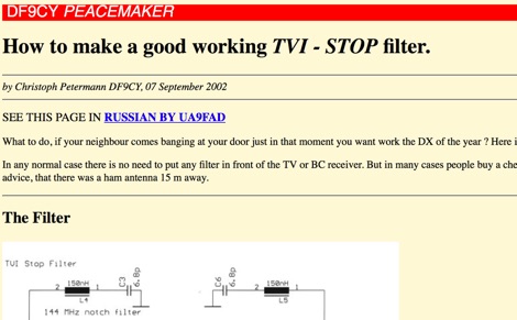 TVI and BCI bandpass and bandstop filters in SMD technique. Schematics and images.
 -
 Sams Photofact downloads - Schematics and Service Manuals for Radios, Amplifiers, More
 -
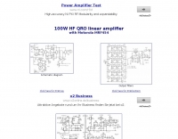
 Advanced QRP Low Cost Mosfets HF Linear Amplifier with schematics, IMD, gain data and more. Six articles about amateur radio.
 -
 The FL-2100Z amplifier referenced in the following images is the 6-Band model covering 10m thru 160m (no WARC bands) and not the 9-Band version that included the WARC bands. Modifications, schematics and manual
 -
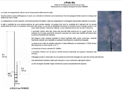 Homebrewed jpole antenna for 50 mhz by IW0BZD, include pictures and schematics, in italian.
 -
 Schematics and purchasing information for the Yaesu FT - 8x7 DIY Bluetooth CAT micro miniature interface done by YO3GGX
 -
 Presents the design and construction of the OK2FJ Bigatas, a portable, automatically tuned vertical antenna covering 80 through 10 meters. It details two distinct control systems: one utilizing BCD band data from Yaesu FT-857/897 transceivers, and another employing voltage level sensing for the Yaesu FT-817. The resource provides specific instructions for building the antenna's radiating element, loading coil with switchable taps, and the control circuitry, emphasizing the use of readily available components. The article outlines the physical construction of the antenna, including the use of duralumin tubes for the radiator and a PVC tube for the coil form. It specifies coil winding details, tap points, and the integration of radial wires for ground plane operation. The control electronics section provides schematics and component lists for both the BCD decoder (using a 74LS42 IC) and the voltage comparator (using an _LM3914_ bargraph driver), enabling rapid, automatic band switching without the minute-long tuning delays common in other systems. Crucially, the antenna achieves rapid band changes, with typical SWR values centered on common operating segments, such as **3.7 MHz** for 80m SSB. It also discusses modifications for CW operation on 80m and the trade-offs between antenna efficiency and full-range automatic tuning on higher HF bands, where manual adjustment of radiator length is suggested for optimal performance on 15m, 12m, and 10m. The resource includes construction photos and a discussion of cable requirements for reliable operation.
 -
 These pages are entirely devoted to the Kenwood TS570 series Transceivers. Specifications & Brochure, Pictures, Schematics, Reviews, Manual and Modifications.
 -
 Presents the detailed construction of the _FLA25HV_ antenna, a specialized array optimized for Earth-Moon-Earth (EME) communications on the 2-meter band. This resource provides schematics and practical insights into building a high-gain antenna system capable of reflecting signals off the lunar surface, a challenging but rewarding aspect of amateur radio. It covers the mechanical and electrical considerations essential for achieving the precise pointing and signal strength required for successful moonbounce contacts, often yielding **20 dB** or more gain. Amateur radio operators pursuing EME operations require robust antenna systems and precise tracking capabilities. The FLA25HV design addresses these needs by focusing on element spacing, impedance matching, and structural integrity to withstand environmental factors while maintaining critical alignment for lunar reflections. Such systems are crucial for making contacts over distances exceeding **768,000 km**. This personal page serves as a practical guide for hams interested in constructing their own EME arrays, offering a glimpse into the technical dedication involved in pushing the boundaries of VHF/UHF propagation.
 -
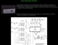 This page displays a 404 error, indicating the original content describing a simple _RS232 interface_ circuit is unavailable. The circuit was reportedly designed for older Kenwood transceivers and featured in chapter 22 of the _ARRL Handbook_. It likely involved basic electronic components for level shifting and signal conditioning between a computer's serial port and the radio's control interface. The intended project would have detailed the construction of a hardware interface, enabling CAT control for specific Kenwood models. Such interfaces typically convert TTL or CMOS logic levels from the radio to the +/-12V levels required by RS232, often utilizing ICs like the MAX232 or discrete transistor circuits. While the specific schematics and bill of materials are absent due to the page error, the context suggests a DIY electronics project for enhancing legacy amateur radio station functionality through computer control.
 -
 Specializes in antique radio schematics and capacitors. carries antique radio schematic diagrams and electronic circuit service information for american, canadian and european antique radios.
 -
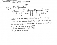
 An RF power supply for 144 MHz schematics and instructions
 -
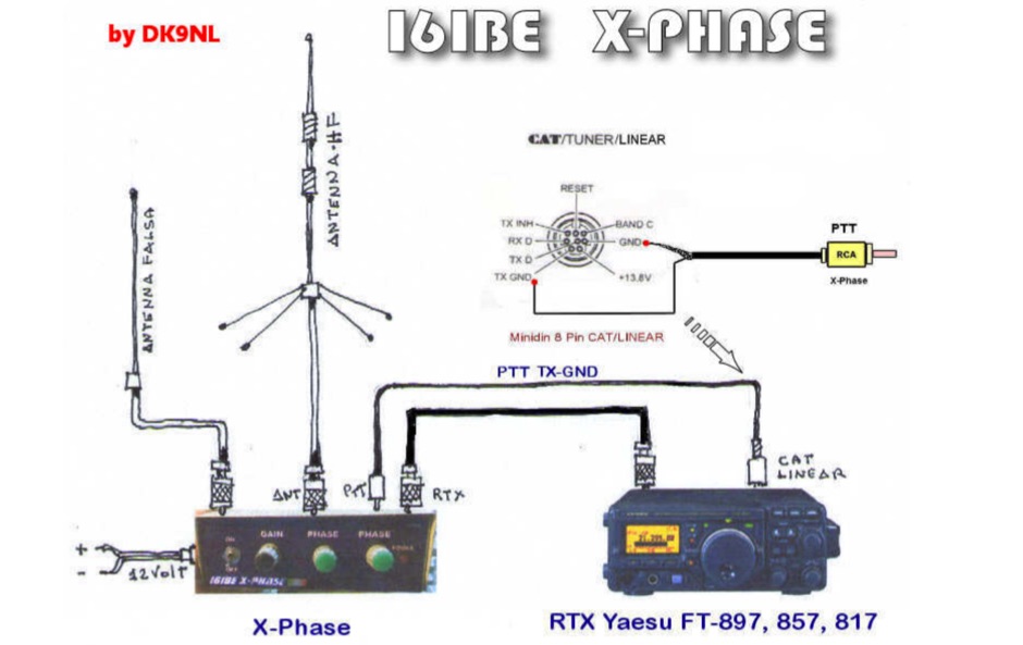 A project with several releases, of the Qkiller or QRM eliminator original project by DK9NL, in italian with schematics, picturs and movies
 -
 A pdf file with schematics of an ssb and cw filter AF amplifier
 -
 WV7U's YC156 and 3CPX800 amplifier projects. Everything you wanted to know about using the YC156 or 3CPX800 in a ham radio linear amplifier. See pictures, schematics, test data, links, and more!
 -
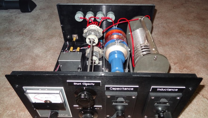 An interesting home made project of an L Network Antenna Tuner Project with pictures and schematics by K7SFN
 -
 Antique Radio Schematics and Service Manuals for Tube Radios
 -
-
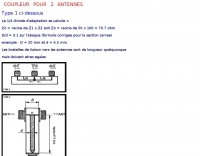
 About different baluns types. Samples and schematics for several ratios baluns in french
 -
-
 Make your own interface, two schematics for building an interface using the RTS line by N3UR
 -
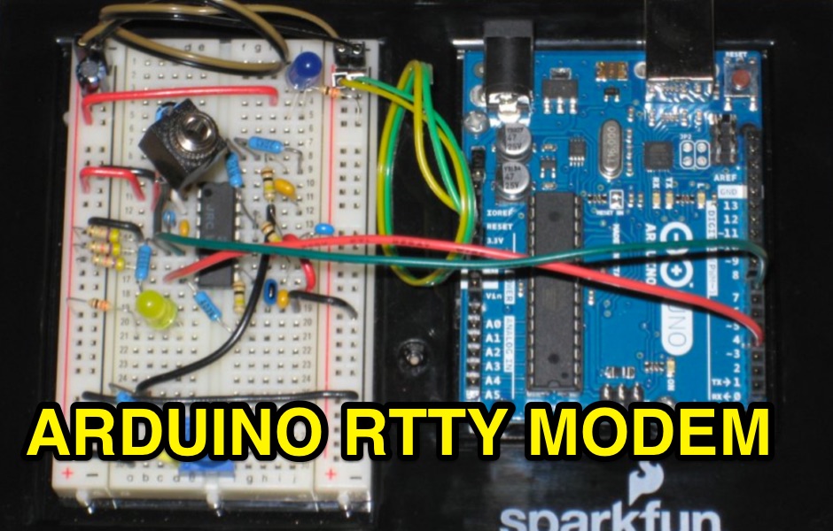 A project for a simple RTTY decoder based on Arduino UNO R3. Includes the RTTY modem source code available for download along to schematics pictures and references.
 -
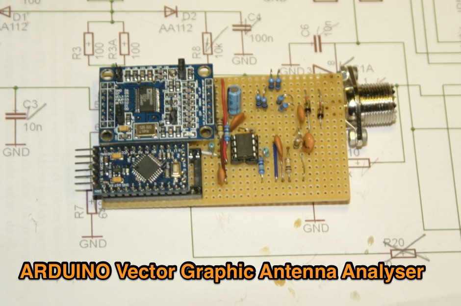 A vector graphic antenna analyzer project page by DC2WK demonstrating a project realized by DG7EAO includes, part list, schematics, and videos.
 -
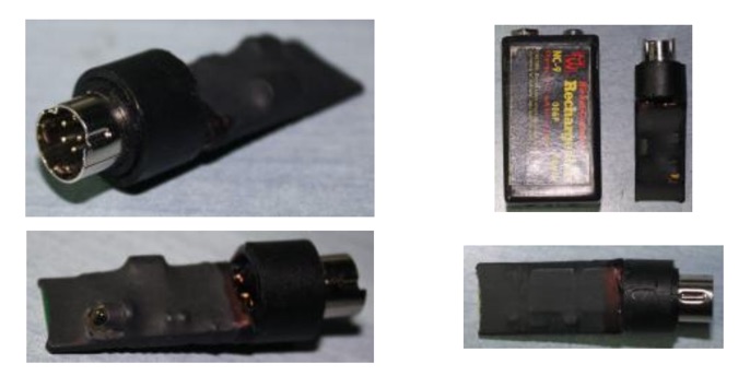
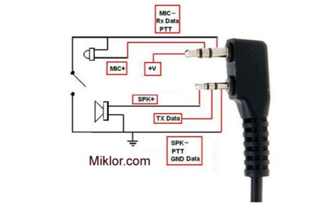 Speaker Microphone Pin Out, Dual PTT Switching,Programming Cables, SMA Antenna Connection, Extended Antenna Threads for Baofeng UV 3, UV 5 Series handheld transceivers
 -
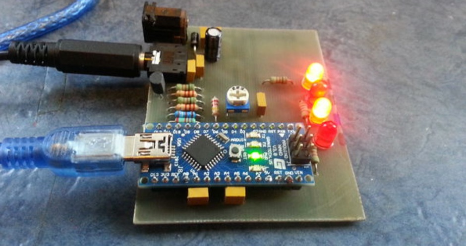 An Arduino TNC modem project based on KI4MCW source code with pictures and schematics