RF Sweep Generators for Filter Testing and Design
Find schematics, projects, and technical information for building and using RF sweep generators in amateur radio applications.
RF sweep generators are essential test instruments for amateur radio operators designing and adjusting filters, amplifiers, and antenna matching networks. These devices produce a signal that continuously varies in frequency over a specified range, allowing hams to visualize the frequency response of their circuits on an oscilloscope or spectrum analyzer. This capability is crucial for optimizing performance across the bands and ensuring equipment operates efficiently.
Many operators enjoy building their own sweep generators, often using common components like the 555 timer for sawtooth waveform generation or even microcontrollers like the Arduino for digital control. Projects range from simple Hartley sweeper designs for narrow bandwidth filter adjustments to more complex heterodyne sweep generators capable of plotting IF filter responses. These homebrew solutions provide practical experience and allow hams to test their antenna projects and transceivers with precision.
-
 A home made sweeping signal generator up to 2 GHz
 -
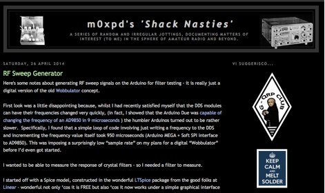 Notes about generating RF sweep signals on the Arduino for filter testing, a digital version of the old Wobbulator concept
 -
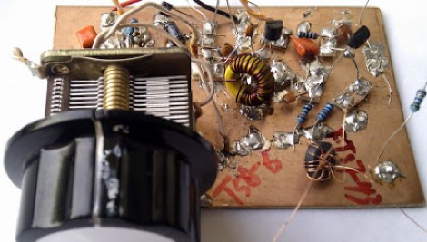
 Hand made RF sweeper made to adjust the pass band of crystal filter
 -
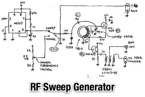 A simple RF sweep generator circuit diagram by JF1OZL
 -
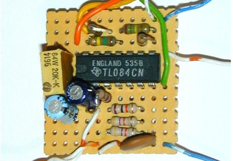
 This sweeper built for a narrow bandwidth filter adjustment, use a simple 555 version sawtooth wave generator.
 -
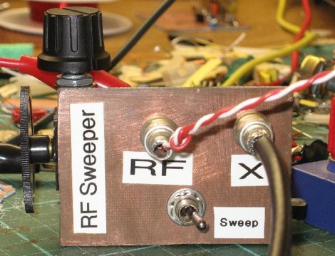
 A sweep generator that produces a sawtooth waveform which sweeps the oscilloscope beam from left to right via its X input, and simultaneously the VCO frequency.
 -
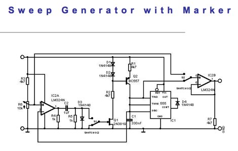 A simple simple sweep generator circuit design where the sawtooth is generated by the PNP transistor and a 555