Clockless Iambic Keyer Circuit Description and Design
Description
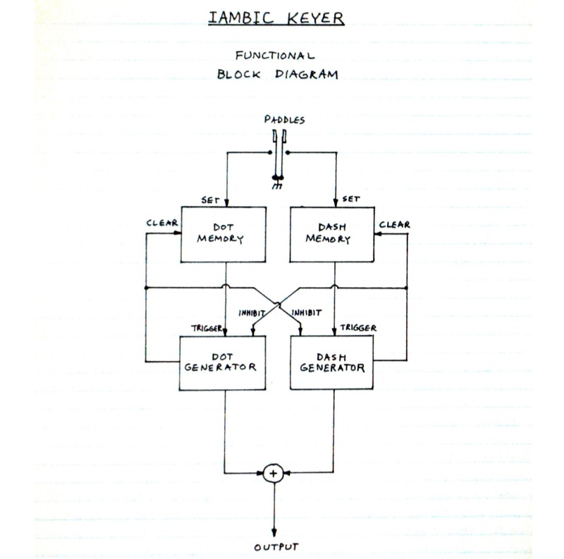
This resource details the circuit design and operation of an electronic Iambic Keyer, generating Morse code from dual-lever paddle inputs. The design incorporates a 7805 regulator (U1) for a stable 5V supply to all integrated circuits. Dot and dash memory latches are implemented using NAND gates (U2A–U2D) to manage paddle input requests and ensure correct Morse element sequencing. Additional logic gates (U3, U4) provide inhibit functions, controlling dot and dash signal generation based on the keyer's operational state. Voltage-controlled current sources, utilizing transistors (Q1–Q4), regulate the charging rates of timing capacitors. Resistors (R1–R4) allow for adjustments to overall keying speed, individual dot and dash durations, and inter-element spacing. The circuit combines logic-based memory, signal control, and adjustable timing for consistent Morse code generation.