Search results
Query: 3 elements yagi for 7 mh
Links: 63 | Categories: 0
-
 A 2 elements yagi beam for 12 meters band with liear load
 -
 6 Elements on 50 MHz / 6 metres
 -
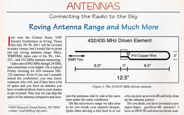 A 18 elements Yagi antenna for 432/435 MHz as published on 2011 CQ VHF magazine
 -
 Antennas for the 1296 MHz based on the construction plans of some Yagis 35 elements by DL6WU, F9FT, DJ9YW. These antennas features a boom of about 3 m and gives a gain of about 17.8 dBd
 -
 A short 3 element LFA Yagi for 50MHz with a 1.94M boom. This antenna has been designed in order to minimise the upward and downward lobes typically seen the the EL plane on Yagi antennas.
 -
 10 Elements Cross-Yagi Antenna for 433 MHz. The base of the 10el antenna is the recalculated RA6FOO antenna.Circular polarization is realized - by a phasing quarter-wave line, matching of horizontal and vertical polarization antennas
 -
 This 10 meter antenna is right out of the ARRL Antenna Book. There are 5 elements on a 24 feet boom and it performs well from 28.0 to 28.9 MHz.
 -
 A Lightweight 2m Yagi for SOTA. The boom is 20mm PVC electrical conduit and the elements are 2.4mm aluminium TIG welding rod. The antenna is carried as a single length of conduit with the elements stowed inside the boom, sealing them in with a bung. The driven element is connected directly to 50 Ohm coax with a BN-43-202 balun core to decouple the coax shield.
 -
 A homebrew 13 elements yagi antenna for two meters band. These project includes two model of the same antenna with a 6 and 7 meter boom length. Detailed pictures and nec files are available for download
 -
 This is a design based on the QuickYagi 4 software by WA7RAI with some changes for practical reasons. The beam uses 6.5 metres of standard 25mm square boom, 12mm diameter elements without tapers. The actual boom length used is 6.3 metres and all parts are readily available.
 -
 This DIY guide details constructing a 5-element Yagi antenna for VHF frequencies. Yagi antennas offer directional signal transmission/reception compared to omnidirectional ones. The guide covers material selection (aluminum, screws, etc.), design using software or formulas, and step-by-step assembly including cutting elements, drilling holes, and attaching the coaxial cable. While calculations are provided for a 146 MHz design, adjustments are necessary for different frequencies. Safety precautions and potential result variations are emphasized.
 -
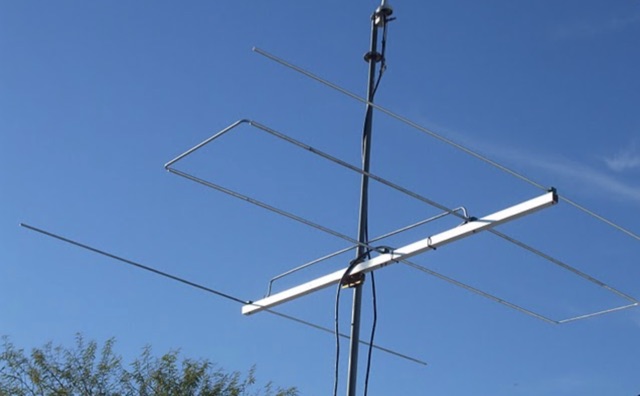
 This project introduces the Loggi, a hybrid antenna merging the wide frequency coverage of log-periodic dipole arrays (LPDA) with the high gain and front-to-back ratio (F/B) of Yagi antennas. Traditional LPDAs span broad frequencies with moderate gain and low VSWR, while Yagis provide high gain and F/B over narrow bands. By analyzing high-Tau LPDA designs, it was found they could nearly match the gain of VHF/UHF Yagis while maintaining excellent patterns, F/B, and front-to-rear ratios (F/R). Optimizing specific elements for target frequencies (e.g., 144.1 MHz) led to the Loggi, which uniquely features all driven elements without passive directors or reflectors. This design effectively functions as a narrowband optimized LPDA, with front elements acting like Yagi directors and rear elements like Yagi reflectors, thus enhancing gain and directional characteristics while retaining broad frequency versatility.
 -
 A home made project for a 7 element yagi antenna for the two meters band based on the DK7ZB original desing.