Search results
Query: microwave radio
Links: 54 | Categories: 13
Categories
- Manufacturers > Microwave
- Shopping and Services > Microwave
- Antennas > Microwave
- Shopping and Services > Antennas > Microwave Antenna
- Manufacturers > Antennas > VHF UHF Microwave > Microwave antennas
- Operating Modes > Aircraft scatter
- DX Resources > Beacons
- Technical Reference > Mircrowave
- Manufacturers > Antennas > VHF UHF Microwave > Mobile Antennas
- Manufacturers > Antennas > VHF UHF Microwave > Quad Antennas
- Ham Radio > Clubs > Technical Specialty
- Manufacturers > Transverters
- Manufacturers > Antennas > VHF UHF Microwave > Yagi Antennas
-
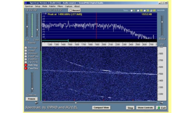
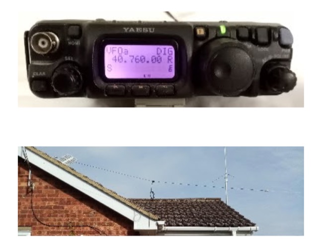 The 8m ISM band, a unique frequency range between 10m and 6m, holds potential for amateur radio enthusiasts, yet it remains largely unallocated. This spectrum offers fertile ground for research and self-training. The author's experience with low-power transmissions and WSPR testing highlights the band's capabilities and the need for a narrow, speech-free amateur allocation to encourage experimentation. Discover the world of 8m ISM radio exploration and its future possibilities.
 -
 Getting started with Aircraft scatter, defined as the process of scatter radio waves of the body of a traveling aircraft in order to enhance the distance possible to bridge on VHF, UHF and microwaves. The ACS path, Equipment requirement and Operating techniques
 -
 The W6PQL 23cm Beacon Project describes a **1296 MHz** beacon designed for microwave propagation studies and equipment testing, capable of 30 watts output. It utilizes a PIC 16F628A microcontroller to generate CW and FSK keying for a crystal oscillator, followed by a series of frequency doublers and triplers to reach the target frequency. The final power amplification stage employs a Mitsubishi M57762 module, providing a robust 10-watt RF output. The design emphasizes stability and reliability for continuous operation, with the microcontroller code, written in assembly, provided for customization of the beacon's callsign and message. Originally located in CM97am and aimed at 140 true, the beacon used four 4-foot Yagis stacked vertically for a total ERP of 3kW. The article includes schematics, parts lists, and construction notes to guide builders, along with antenna pattern measurements. Although the beacon itself is no longer in service as of August 2010, the detailed documentation remains a valuable reference for amateur radio operators interested in building similar **microwave** projects or understanding beacon operation.
 -
 This online construction guide details the assembly of a signal generator specifically for the **13cm band** (2.4 GHz). The curriculum focuses on the integration of a Voltage Controlled Oscillator (VCO), specifically the ROS-2400, to produce a stable RF signal. The resource outlines the necessary components for frequency generation and output, including the use of a Mini-Circuits MMIC amplifier for signal conditioning. The construction protocol involves configuring the ROS-2400 VCO to operate within the 2.3 GHz to 2.45 GHz range, ensuring frequency coverage for amateur radio _microwave experimentation_. The guide specifies the output power level, approximately 70mW, directly from the MMIC stage, indicating its application as a low-power instrumentation source rather than a transmit-capable device. This project provides a practical example of constructing a dedicated test instrument for microwave frequency measurements and system alignment on the **13cm band**. DXZone Focus: Construction Guide | 13cm Signal Generator | VCO Integration | Microwave Experimentation