Search results
Query: 1:1 ferrite current balun
Links: 6 | Categories: 0
-
 Operating a ZS6BKW antenna often involves understanding its lineage from the _G5RV_ design, with specific modifications by ZS6BKW to optimize performance on several bands. Through computational analysis and field measurements, the antenna's dimensions were refined to allow operation on 10, 12, 17, 20, and 40 meters without an antenna tuner. For 80, 30, and 15 meters, a tuner is necessary, though efficiency on 30 and 15 meters is noted as not particularly high. The physical configuration consists of two 13.755-meter radiating elements fed by a 12.20-meter section of 450-ohm ladder line. Tuning the antenna on the 20-meter band is critical, and any deviation in the ladder line's characteristic impedance necessitates recalculating the element lengths. The design is also referenced in the 12th edition of _Rothammel's Antennenbuch_, page 219. Proper common mode current suppression is crucial at the transition from ladder line to coaxial cable. This can be achieved with a common mode choke, such as several turns of coax wound into a coil or over a ferrite toroid like an Amidon T130. While a 1:1 balun is an option, it may introduce issues.
 -
 Optimizing a G5RV or ZS6BKW multiband wire antenna for HF operation often involves addressing common SWR issues and understanding feedline characteristics. This resource chronicles the construction and performance evaluation of a G5RV, initially built for 80m, 40m, 15m, and 10m bands, by a newly licensed Foundation operator. The author details the selection of materials, including 3.5 mm stainless steel wire for the doublet arms and enameled copper wire for the open-wire feeder, and the initial decision to omit a balun based on common online information. The narrative highlights the initial disappointing performance, characterized by high receive noise and poor signal reports on 80 meters, despite the transceiver's internal ATU achieving a 1:1 match. This led to experimentation with a coax current balun and further research into G5RV myths, such as SWR claims and the necessity of a balun. The author then describes modifying the antenna to the ZS6BKW configuration, which involves specific changes to the doublet and feedline lengths, and integrating a 1:1 current balun wound on a ferrite toroid. The modifications resulted in improved reception and transmit performance across the bands.
 -
 The AE6AC 17-meter Moxon antenna project details the construction of a wire beam using readily available materials. This design utilizes four 16-foot fiberglass crappie poles for support, joined at the center with 3/4-inch Schedule 40 PVC pipe and "T" slip fittings. Wire segment lengths for 18.135 MHz were calculated using _Moxgen_ software by AC6LA, with specific dimensions provided in feet and inches for precise cutting. Key construction decisions include joining the crappie pole bases into a central hub and attaching the 16-gauge silver-plated copper wire to the pole ends. Dacron cord with a fisherman's knot secures the wire to the pole tips, while small wire loops at the corners maintain antenna shape. Plexiglas pieces serve as insulators for sections "A" and "C." The finished antenna, weighing less than 10 pounds, mounts on a fiberglass windsurfer mast and incorporates a 1:1 current mode ferrite bead balun. Performance measurements with an _MFJ-259B_ show an SWR better than 1.5:1 across the 17m band, with good front-to-back ratio and reported signal strength improvements of 2-4 S-units over vertical dipoles. Initial contacts included VK2AXB, ZF6GS, and KL1M.
 -
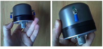 Presents a construction project for a 1:1 current balun, specifically detailing the _Sorbie Balun and Bottle Choke_ design. The resource outlines the winding technique, employing 4+4 turns of mini coaxial cable on a large ferrite core, and provides insights into the physical assembly. It includes specific material recommendations, such as the type of ferrite and coaxial cable, crucial for achieving the desired impedance transformation and common-mode current suppression. The content covers the practical steps involved in building the balun, from preparing the coaxial cable to securing the windings on the ferrite toroid. It also discusses the integration of the balun into an antenna system, emphasizing its role in maintaining pattern integrity and reducing RF interference in the shack. The resource offers a clear, step-by-step approach, making the project accessible for homebrewers. Illustrations and photographs accompany the text, visually guiding the builder through each stage of construction. The article concludes with performance expectations and considerations for deployment, ensuring the constructed balun functions effectively across the intended frequency range.
 -
 This comprehensive three-part guide examines baluns (balanced-to-unbalanced devices) and their critical role in ham radio antenna systems. The author explains how baluns prevent common-mode currents on feedlines, which can distort radiation patterns and cause unwanted RF in the shack. Various balun types are analyzed, including coiled coax chokes, ferrite-core designs (W2DU), and toroidal-wound versions (Guanella/Ruthroff). Construction techniques for 1:1, 4:1, 6:1, and 9:1 current baluns are provided with practical guidance on wire selection, winding methods, and ferrite core properties. The article emphasizes that proper balun implementation is essential for optimal antenna performance, especially with directional arrays.
 -
 VE2AZX's 2013 Radio Talk presentation details the technical aspects of baluns, including reasons for their use, various types, and methods for performance verification using an SWR analyzer. The document specifically examines 1:1 voltage baluns and 4:1 voltage baluns, outlining their winding configurations and typical impedance transformations. It presents empirical SWR measurements for W2AU 1:1 baluns and Unadilla 4:1 baluns, tested with both 50-ohm and 200-ohm resistive loads across the HF spectrum. The presentation further explores the measurement of ferrite impedance and their application in mitigating common-mode currents on feeders and household conductors. Key concepts addressed include balanced-to-unbalanced transformation, ensuring feeder independence from the antenna, and reducing unwanted feeder radiation. The content emphasizes practical testing procedures to ensure optimal antenna system performance and minimize RF interference. Discussions also cover open-circuit tests with SWR analyzers and VNAs to assess winding inductance, distributed capacitance, and insulation quality. The presentation differentiates between voltage and current baluns, explaining how current baluns, particularly those utilizing ferrite cores, reduce outer shield currents without affecting internal coaxial cable currents, thereby preserving the antenna's intended radiation pattern.