Search results
Query: 14 mhz pa linear
Links: 6 | Categories: 0
-
 The G5RV antenna, with an overall length of **31.10m (102ft)**, functions as a 3/2-wave on 20 meters when installed horizontally at 12m (39ft), exhibiting a resonant frequency of 14.150MHz and an approximate resistance of 80 ohms. Its 10.36m (34ft) stub line, designed as a 1/2-wave on 14.150MHz with a 0.97 velocity coefficient, acts as an impedance transformer across other bands, aiming for multiband operation without traps. On 20m and higher frequencies, the G5RV demonstrates improved gain compared to a standard dipole, attributed to the _collinear effect_ from multiple 1/2-waves along the wire. The original design sought a multiband solution for limited spaces, often requiring an Antenna Tuning Unit (ATU) for effective operation across bands like 80, 40, 30, and 20m, particularly with modern solid-state PAs. Variants, such as the F8CI modification, incorporate a 1/4 current balun at the stub line's base for symmetrical-to-asymmetrical transition, known as a _remote balun_. Proper flat-top or inverted-V installation is critical for maintaining symmetry and collinear gain, with inverted-V apex angles below 120° progressively diminishing higher-band performance.
 -
 A 144 MHz kilowatt amplifier project details the construction and performance of a high-power VHF linear using the GU74b tetrode. This Russian tube, equivalent to the Svetlana 4CX800, is noted for its conservative datasheet ratings, performing closer to 800-1000W anode dissipation in practical applications. The design prioritizes compactness and achieves 1.2 kW output with only 20W of drive power, demonstrating a 70% efficiency at 2.5 kV plate voltage. The amplifier has been successfully deployed in demanding _EME_ (Earth-Moon-Earth) operations since June 1994. Challenges encountered during development included achieving stability with a grid-1 input configuration. The author, _CT1DMK_, opted not to publish the full design due to its complexity, suggesting it might be difficult for less experienced builders to replicate successfully. However, he invites direct contact for those with specific interest in the design. Future plans include a "144MHz GS35b compact amplifier" project, promising another kilowatt-plus design. This resource offers insights into high-power VHF amplifier construction and the practical application of specific power tubes.
 -
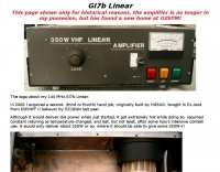 A 400 W 144 MHz GI7b Linear amplifier
 -
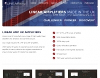 Linear Amp UK specializes in the design and production of high-quality linear amplifiers, offering models for HF, VHF, and UHF amateur and commercial applications. The company emphasizes nearly 30 years of experience in crafting each unit, ensuring robust performance and longevity. Their product line includes amplifiers engineered for a 100% duty cycle, promoting continuous and reliable operation across various modes. The amplifiers feature solid, dependable designs, ensuring quiet and effortless performance during transmission. Each unit is hand-built to stringent standards, reflecting a commitment to durability and operational stability. All products are CE approved, confirming compliance with European safety and environmental directives, and come with a standard two-year warranty, providing assurance to operators. Key specifications often include coverage for 1.8-30MHz (WARC bands), 50MHz, 70MHz, and 144MHz, utilizing tubes such as 811, 572, 811A, 572B, GS35, GS35B, 8877, 3CX1500, and _3CX1500A7_ in their designs.
 -
 This article details the design and construction of a compact 20-meter QRP SSB transceiver by Pete Juliano, N6QW, measuring just 2 x 4 x 2 inches—small enough for a shirt pocket. Inspired by a 1963 QST design and refined from a prior version, it employs bilateral circuits, a 4.9152 MHz homebrew crystal filter, switched-crystal VXO for 60 kHz coverage (14.160-14.220 MHz), and standard components like ADE-1L mixers and IRF510 PA for 1W output. Key innovations include a double-sided PCB skeletal frame for shielding and isolation, Vectorboard sub-assemblies, and ultra-miniature relays. The bilateral receiver/transmitter shares stages, omitting AGC for simplicity, while a W3NQN LPF and optional 10W external amp enable DX contacts. Tune-up focuses on crystal matching and bias for linearity. Videos on YouTube demonstrate performance, confirming excellent stability and audio. Total cost nears $100, prioritizing portability over features like CW.
 -
 The Olivia digital mode, a **Multi-Frequency Shift Keying (MFSK)** radioteletype protocol, is specifically engineered for robust communication under difficult propagation conditions on shortwave radio bands from 3 MHz to 30 MHz. Developed by Pawel Jalocha in 2003, Olivia signals can be decoded even when the noise amplitude exceeds the digital signal by over ten times, making it highly effective for transmitting ASCII characters across noisy channels with significant fading and propagation phasing. Early on-the-air tests by Fred OH/DK4ZC and Les VK2DSG on the Europe-Australia 20-meter path demonstrated intercontinental contacts with as little as one-watt RF power under favorable conditions. Common Olivia modes are designated as X/Y, where X represents the number of tones and Y is the bandwidth in Hertz, with examples including 8/250, 16/500, and 32/1000. The resource clarifies that Olivia, unlike some other digital modes, produces a constant envelope, allowing RF power amplifiers to achieve greater conversion efficiencies and making it less prone to non-linearity. Operators are advised that **Automatic Level Control (ALC)** can be set higher than no meter movement for MFSK modulation, as long as it's not driven past its high limit, contrary to common misinformation about other digital modes. The Olivia community encourages voluntary channelization on suggested calling frequencies, such as 14.0725 MHz for 8/250, to facilitate initial contacts, especially for signals below the noise floor. The Olivia Digital DXers Club provides links to Groups.io, Facebook, and Discord for community engagement and offers details on QSO parties.