Search results
Query: 222 5 band
Links: 6 | Categories: 0
-
 Rhombic Antenna dimensions for HF and VHF bands by N6JSX
 -
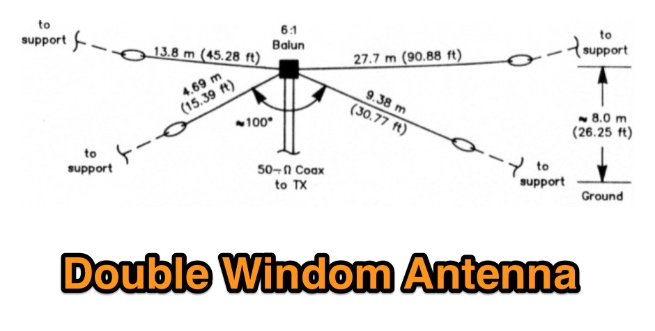 A project for a multiband HF windom antenna by VE2CV and VE3KLO
 -
 Demonstrates the construction of a custom programming cable for Yaesu VX-7R and VX-5R handheld transceivers, enabling computer interfacing for memory management and frequency coverage adjustments. The resource details a six-transistor circuit design, powered by the computer's RS232 interface, utilizing readily available and inexpensive discrete components. It includes a complete bill of materials, specifying transistors like the _2N2222_ and _2N3906_, diodes, and resistors, along with a matrix board layout for compact assembly within a 75x50x25mm enclosure. The guide provides practical tips for working with matrix board, such as scoring and snapping, track cleaning, and component soldering order. It outlines the specific connection requirements for both the VX-7R (via Yaesu's CT-91 breakout lead with a 2.5mm stereo jack) and the VX-5R (via CT-44 or a four-section jack), detailing signal and ground pinouts. The author successfully tested three circuits, documenting the one with complete two-way communication, allowing users to program their rigs with software like _VX-7 Commander_ and achieve capabilities beyond commercial cables, including band adjustments.
 -
 High power, UHF, L-band, S-band, C-band, microwave frequency amplifier and oscillator devices, pulsed, CW, fixed-tuned, or tunable devices in the range of 600 MHz to 2000 MHz
 -
 Experimental Long Boom Antennas - CP, LPDA, multiband with several NEC Files for 50MHz 144MHz 222 MHz 432MHz but also 902MHz and 1296 MHz Antenna projects. Includes also for each antenna model, in a general comparison table each antenna characteristics including Directive Gain, G/T, E-F/R, H-F/R abd Boom Length. This is a great value comparison table of several commercial and home made VHF UHF antenna projects.
 -
 The 222 MHz Transverter project, based on Zack Lau's (W1VT) original July 1993 QEX magazine design, provides an IF of 28 MHz for both transmit and receive paths. Rick Bandla (VE3CVG) contributed supplemental notes and construction details, including modifications to achieve 10 mW output power from an initial 4 mW PEP. The design incorporates three distinct boards: a Local Oscillator (LO), a Transmitter (Tx), and a Receiver (Rx), with an estimated parts cost of just over $150 CDN, significantly less than commercial kits. Construction involves both through-hole and surface-mount components, with specific guidance on mounting MAV and MAR devices, grounding techniques, and component selection. The project details include parts lists, schematics for the LO, Tx, and Rx, and board layouts. Troubleshooting advice emphasizes sequential testing, starting with the LO, then Tx, and finally Rx, using a 194 MHz and 222.100 MHz capable FM handheld for signal tracing. Further enhancements are discussed, such as an optional Tx driver stage to boost output to 100 mW and the potential modification of a Motorola Maxor 80 PA for 222 MHz SSB/CW operation. The resource also covers practical aspects like power attenuation pads for IF radios (e.g., FT817) and considerations for enclosure design, including repurposing a Maxor 80 case. Performance reports indicate successful 70 km contacts with only 4 mW output.