Search results
Query: 450 ohm twinlead
Links: 3 | Categories: 0
-
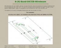 This wire-beam has one radiator-element, feeded with 450-Ohm-Wireman-twinlead and needs an antenna-tuner. For the bands 6m, 10m, 12m, 15m, 17m and 20m bended reflector-elements are used. The support is a cross of 4 fibreglass-fishing-rods
 -
 Demonstrates the ZS6BKW multiband HF antenna, a design by ZS6BKW (G0GSF) that improves upon the G5RV by offering direct resonance on multiple bands without an antenna tuner. The resource details the antenna's 90-foot length and 40-foot 450-ohm twin lead downlead, emphasizing its suitability for hams with limited space or budget. It covers both horizontal and inverted-V configurations, noting the inverted-V's single-support advantage and the importance of maintaining an apex angle of at least 90 degrees to prevent signal cancellation. The author, G3UKV, shares his preference for 450-ohm twin lead over 300-ohm due to its superior strength and lower losses, especially in wet conditions, drawing from his extensive field experience. The document presents recorded SWR and impedance (R) measurements taken with an MFJ Antenna Analyzer, confirming excellent performance on 40m, 20m, 17m, 12m, 10m, and 6m, often with SWRs below 1.3:1. It also discusses the antenna's tunability on 80m with an ATU and suggests a method for 160m operation. G3UKV recounts receiving "excellent reports" on 7 MHz and 14 MHz, validating the antenna's effectiveness. Practical advice includes keeping antenna ends clear of ground by at least a yard to avoid detuning and the recommendation of a 1:1 current balun where the 450-ohm feeder connects to 50-ohm coax.
 -
 Constructing a **J-Pole antenna** from 450 Ohm ladder line for 2-meter (144 MHz) and 70-centimeter (440 MHz) operation involves specific calculations and assembly steps. The design, based on an earlier KD6GLF concept using 300 Ohm twinlead, features a ¾ wavelength radiator and a ¼ wavelength matching stub, functioning as an end-fed half-wave antenna without requiring ground radials. It offers a gain of 2.4 dB over isotropic. The resource provides the formulas for determining the lengths of the ¾ wave radiator and ¼ wave stub, incorporating a velocity factor of 91% for 450 Ohm ladder line. For 146 MHz, the radiator measures 55 3/16 inches and the stub 18 3/8 inches. Construction details include cutting a 57¾-inch piece of ladder line, stripping 4 inches from one end, and attaching a 24-inch section of RG58 or RG8X coax with a 3-5 turn RF choke. SWR adjustment is achieved by sliding a shorting bar or by incrementally trimming the elements at a 1:3 ratio (stub to radiator). The goal is a 1:1.1 SWR at 146 MHz, which typically yields 1:1.2 at 446 MHz. The article also discusses power handling, noting that while 10-15 watts is fine, 50 watts may increase SWR to 1:2.1, and advises keeping the antenna away from other objects to prevent coupling and SWR degradation.