Search results
Query: 50mhz amp
Links: 13 | Categories: 0
-
 A 6 meters band amplifier width schematics
 -

-
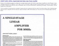 G3WZT design for a single stage bi-polar 100-150W Linear Power Amplifier for the 6M band.
 -
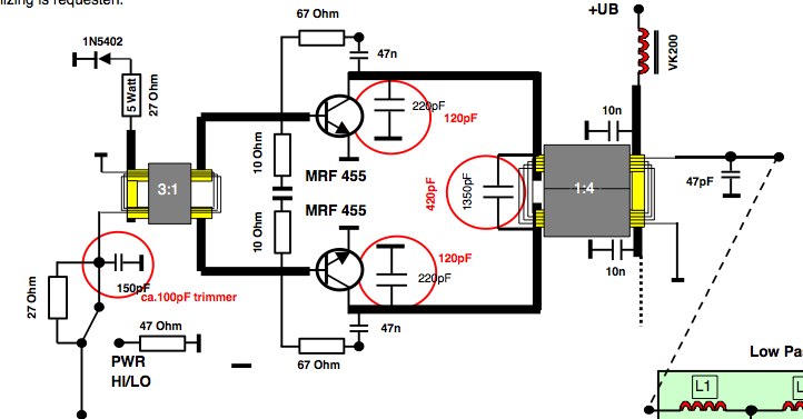 Converting a ZETAGI B303 power amplifier for 50 MHz usage
 -
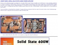 G3WZT design for a bi-polar 600W Linear Power Amplifier for the 6M band.
 -
 A Compact 8877 50MHz amplifier and Power supply
 -
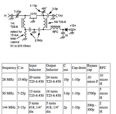 Extremely reliable FET preamplifier can handle several watts directly into either the input or the output without failure
 -
 Tests on a preamplifier for 50 MHz installed right at the feedpoint of the antenna.
 -
 An high gain long yagi antenna, seven elements, for six meters band
 -
 Linear Amp UK specializes in the design and production of high-quality linear amplifiers, offering models for HF, VHF, and UHF amateur and commercial applications. The company emphasizes nearly 30 years of experience in crafting each unit, ensuring robust performance and longevity. Their product line includes amplifiers engineered for a 100% duty cycle, promoting continuous and reliable operation across various modes. The amplifiers feature solid, dependable designs, ensuring quiet and effortless performance during transmission. Each unit is hand-built to stringent standards, reflecting a commitment to durability and operational stability. All products are CE approved, confirming compliance with European safety and environmental directives, and come with a standard two-year warranty, providing assurance to operators. Key specifications often include coverage for 1.8-30MHz (WARC bands), 50MHz, 70MHz, and 144MHz, utilizing tubes such as 811, 572, 811A, 572B, GS35, GS35B, 8877, 3CX1500, and _3CX1500A7_ in their designs.
 -
 A 50MHz kW Amplifier by Goran Grubishic, 9A6C
 -
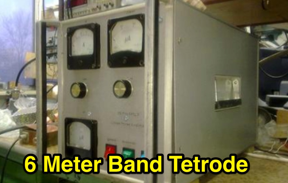 Demonstrates the construction of a high-power 6-meter (50 MHz) amplifier, specifically designed for demanding modes like EME, TEP, and multiskip Es. It details the use of a _GU-43B_ tetrode in a grounded-cathode configuration, emphasizing the need for stabilized grid voltage and input capacitance compensation. The resource provides a comprehensive schematic, power supply design, and practical considerations for component sourcing, particularly for high-voltage and high-current sections. The builder achieved an output power of **1250 watts** with an anode current of 0.65 amperes and 3200 volts anode voltage. The article also covers the physical construction within a modified P6-31 enclosure, outlining the internal layout for RF and power supply sections, and includes photos of the completed unit. It highlights critical safety precautions for working with high voltages and reactive currents up to **20 Amperes** in the P-network.
 -
 Manufacturer of 50MHz, 70MHz, 144MHz, 222MHz, 432MHz, 900MHz or 1.2GHz transverters and VHF UHF amplifiers