Search results
Query: 70mhz antenna
Links: 20 | Categories: 0
-
 Build your own antenna for the 23cm band ( 1250Mhz - 1280Mc ) using some aluminium and this simple design.
 -
 This project details three variants of a vertical half-wave antenna design for the 4-meter (70MHz) amateur radio band. The antennas use end-feeding with a parallel-tuned circuit for impedance matching to 50-ohm coaxial cable. The first variant uses suspended flexible wire for portable use, the second employs a fiberglass rod with internal wire for permanent outdoor installation, and the third utilizes aluminum tent poles for quick mobile deployment. Despite the narrow bandwidth of the matching circuit, this suits the narrow 4m FM allocation well. The design offers an effective omnidirectional radiation pattern and can be constructed with readily available materials.
 -
 This article describes the construction of a Moxon rectangle antenna for the 70MHz (4-meter) amateur radio band. This compact two-element beam design features folded element ends, reducing its width to approximately 75% of a half-wavelength. The antenna was built using enamelled copper wire stretched over a lightweight fiberglass kite spar frame, with a direct coaxial cable feed connection. Initial testing showed a VSWR of around 1.3 with distinct nulls at 90 degrees when horizontally mounted. The author later tested vertical polarization and suggested that the antenna's compact size might allow for indoor loft installation.
 -
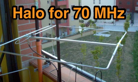 Halo antenna for 4 meters band with dimensions, pictures and assembling instructions
 -
-
 Dutch Antenna and Tower Manufacturers from Slimline Square Triangular Round Towers. Antennas production include Yagi Monoband/Dipole/HF Quad /50MHz and 70MHz Yagi-Quad, VHF-UHF yagi-Quad and Comby antennas VHF/UHF/SHF
 -
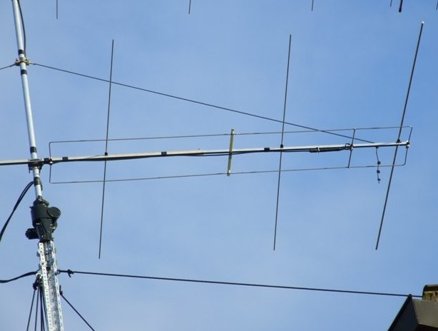
 This document details the design and construction of a Vinecom 6N4 dual-band Yagi antenna for the 50MHz (6-meter) and 70MHz (4-meter) amateur radio bands. The antenna features 9 total elements (4 elements for 50MHz, 5 elements for 70MHz) on a 4.236-meter aluminum boom. Computer simulations using MMANA software predict 7.21 dBd gain on both bands with front-to-back ratios of 16.01dB (6m) and 15.37dB (4m). The design uses 12.7mm diameter elements mounted on a 32mm square boom, weighing 5.7kg total. Practical measurements with an MFJ-269 analyzer confirmed good SWR performance across both bands after element length adjustments.
 -
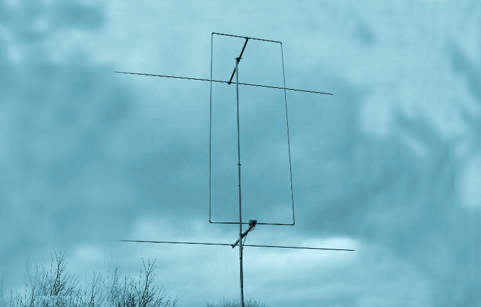 The Quadlong antenna for the six meter band. This antenna feature a total gain of 6,4 dBd, F/B 21 dB and is also available in 70MHz version. Includes detailed pictures and plot diagrams.
 -
-
 Demonstrates the adaptation and construction of a 7-element DK7ZB Yagi antenna for the 4-meter band (70 MHz), utilizing components from a defunct 2-meter CUE DEE Yagi. The resource details the modifications made to the original DK7ZB design to fit the shorter CUE DEE boom length, specifically adjusting element lengths for 6mm rod elements while reusing existing mounting holes for the reflector and last director. It provides precise element lengths for the reflector, dipole (12mm aluminum tube), and five directors, along with a note on cutting elements for transport. The article includes a 4NEC2 simulation file for performance analysis and an SWR plot, confirming the antenna's electrical characteristics. It also specifies the calculation for the quarter-wavelength matching cable using SAT752F coaxial cable, resulting in a 909mm length. Practical application is shown with the finished antenna in operation at JO20XC, listing several activated Maidenhead squares such as JO56PA and JP40KS, validating its effectiveness for portable 70 MHz operations.
 -
 A 5 elements homemade DK7ZB yagi antenna for 4 meters band based on a 50MHz TONNA
 -
 5-element antenna, with which G0JJL has worked lots of EU crossband, and won the RSGB Christmas Cumulatives 70MHz section twice in a row.
 -
 This web article details the construction of a 4-meter band coaxial dipole antenna, designed for operation between **70.000 MHz and 70.500 MHz**. The resource provides a bill of materials and step-by-step assembly instructions for a half-wave dipole constructed from _RG-58_ coaxial cable. The design specifies a direct 50 ohm feedpoint impedance, eliminating the need for an external matching network. Construction photographs illustrate the stripping and soldering processes for the coaxial cable elements, ensuring proper electrical connection and physical integrity. The article includes specific dimensions for the radiating elements, derived from calculations for the 70 MHz band. The project outlines the physical dimensions required for resonance at 70 MHz, with the outer braid forming one half and the inner conductor forming the other. The feedline connection is directly to the coaxial dipole's center, maintaining a 50 ohm characteristic impedance. While the article does not present SWR plots or VNA sweeps, it focuses on the mechanical construction and dimensional accuracy for achieving a functional 4-meter dipole. The design is intended for fixed station use, with no specific mention of polarization or height above ground, but implies a standard horizontal orientation for dipole operation. DXZone Focus: Web Article | 4m Coaxial Dipole | Construction Guide | 50 ohm Feed
 -
 Pictures, design plan and description of a 5 element yagi antenna for the 4 meters band by 9A7PJT
 -
 A Yagi-Mag antenna for the 4 meters band with NEC and MMANA files plans and pictures
 -
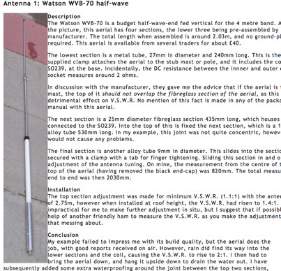 A comparison of commercial 4m verticals by by Ian Hogan G6TGO
 -
 This multiband transverter project features power output at 13,8V 50MHz 15W, 70MHz 10W, second harmonic < 65dBc. Single N connector of antenna, suitable for a dual band Yagi. Article include Block Diagram for Dual Transverter and low pass filters
 -
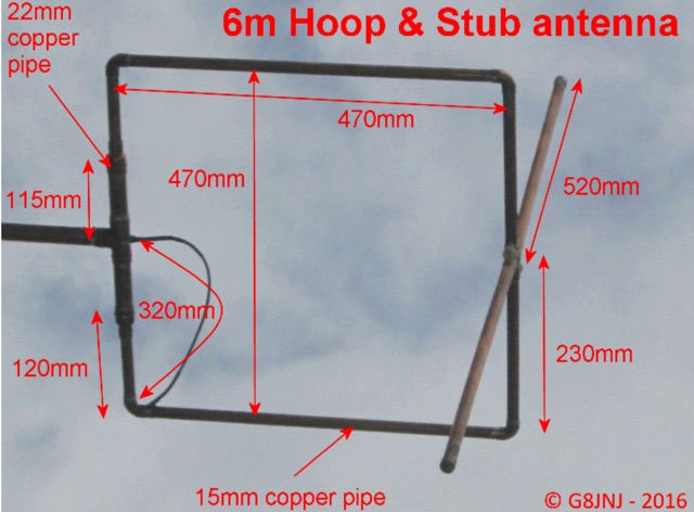 Omni-directional mixed polarisation antenna for 50MHz & 70MHz. This is a simple Halo and Stub antenna which provides an omni-directional radiation pattern with mixed polarisation, which I built for use with the SUWS WEB SDR
 -
 A homemade quarter wave ground plane anntenna for 4 meters band.
 -
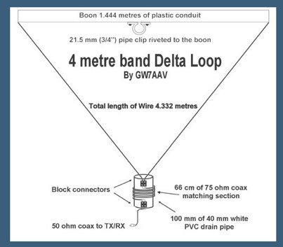
 Discover the success story of creating a 4-meter Delta Loop antenna, ideal for improving radio communication. This horizontally polarized antenna offers efficient performance when mounted at VHF heights, catering to both HF and VHF characteristics. A simple, DIY project suitable for portable setups, providing versatile options for radio enthusiasts.