Search results
Query: high voltage transformer
Links: 3 | Categories: 0
-
 Operating in a Single Operator Two Radios (SO2R) setup, especially with beverage antennas, often exposes the receiving radio's front-end to significant RF energy from the transmitting radio. This resource details a practical, homebrew receiver protection circuit designed to mitigate this risk. The core of the design involves a non-inductive 2W 22 Ohm carbon composition resistor in series with the RX antenna line, followed by two stacks of four fast-switching diodes (e.g., _1N914_) configured in opposite polarizations. This arrangement effectively clamps the incoming voltage to approximately 2.8 V peak-to-peak, safeguarding sensitive receiver input components. The series resistor plays a crucial role by absorbing excess power, preventing the diodes from exceeding their current ratings and potentially failing open, which would leave the receiver unprotected. The author, _N4KG_, measured up to 50 watts of coupled power between 80M slopers on the same tower, highlighting the necessity of such protection. The design is presented as a cost-effective solution to prevent damage to receiver input transformers, with the author noting successful protection of a receiver even after a resistor showed signs of overheating. This simple circuit can be integrated via a transverter plug, offering a robust defense against high RF input.
-
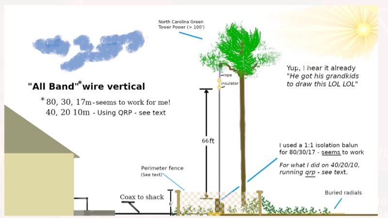 WB8LZR details the construction and initial field results of a multi-band vertical wire antenna, designed to complement his existing horizontal loop for improved DX on 80 meters. The antenna utilizes a 67-foot vertical wire, configured as a quarter-wave radiator on 80m, and employs a 1:1 current balun for RF isolation on 80m, 30m, and 17m. For bands like 40m, 20m, and 10m, where the wire acts as a half-wave or full-wave radiator, an additional impedance transforming _unun_ is integrated to manage the significantly higher feedpoint impedance and voltage. The author notes the vertical's performance as a receiving antenna, observing reduced noise compared to his main horizontal loop, particularly on 80m, and even hearing some long-path signals the loop missed. Initial QRP contacts, including a **1-watt** QSO with a _VP2 station_ on 30m, demonstrate its transmit capability. While the radial system is currently rudimentary, the project outlines practical considerations for multi-band vertical deployment and impedance matching.
-
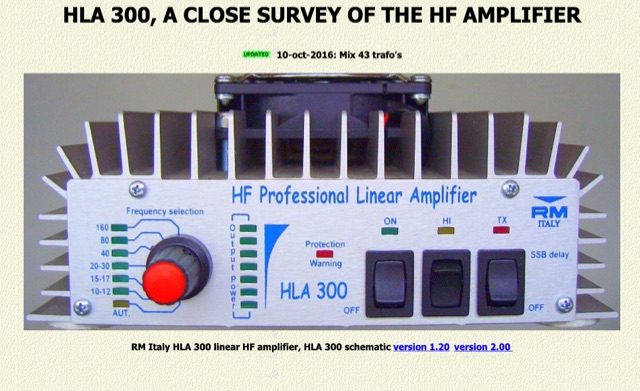 The RM Italy HLA 300 linear HF amplifier, a solid-state unit designed for 12-14 V operation, is examined through practical experiences and test results. This survey highlights key operational aspects, including the necessity of the ventilated 'V' version for effective cooling, which operates quietly on standby and engages immediately on transmit. Manufacturer specifications claim 300 W CW output with 1-15 W input and 550 W SSB output with 2-20 W input, making it a robust option for many HF operators. PH4U/DC2DC's field tests on his HLA 300, an all-band/all-mode transistor amplifier drawing 45 A, provided valuable insights into its real-world performance. The amplifier features six low-pass filters, covering nine HF bands, a notable inclusion compared to many similar products. Testing revealed that a 1-Volt drop in the 12-14V supply, common with high currents (45-55 Amps) and inadequate cabling, can significantly impact output power, with a 50 W increase observed when voltage rose from 12 V to 13 V under load. Observations also noted that driving the HLA 300 with only 5 W, such as from an FT-817, is insufficient to reach its full potential, suggesting an intermediate amplifier stage is needed to achieve the recommended 20 W input. Modifications, such as removing a 100 pF capacitor, improved performance, and replacing output transformers with BN43-7051 (mix 43) ferrites significantly reduced distortion, as evidenced by spectrum analyzer images from PA1HR's HLA 150 modification.