Search results
Query: microphone wiring
Links: 17 | Categories: 2
-
 Microphone wiring can be a pain if your not sure how to work out which wire goes where
 -
 Alan Cobra Uniden President Galaxy and more microphone wiring diagrams
 -
 Roy G4WPW has collected one of the most complete and interesting pages for microphone connections schemas and wiring. Includes Kenwood microphones schematics as well as Yaesu Icom Alinco Adonis Drake Heil JRC MFJ schematics
 -
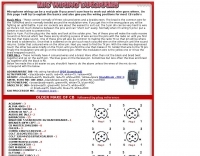
 This page discribes microphone wiring connections for most UK and foreign radios. Most U.S. radios are "Code Type 2".
 -
-
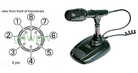 Yaesu MD-100 microphone schematic wire diagram with pin out
 -
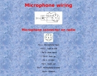
 This online guide details the microphone pinout for the Kenwood TR-7950 transceiver, specifically addressing the wiring configuration for a dynamic mobile microphone with a **500 Ohm** impedance. It provides a pin-by-pin breakdown for the 6-pin microphone connector, identifying the function of each active pin. The resource specifies that Pin #1 is for the microphone audio (white wire), Pin #2 controls the _PTT_ (black wire), Pin #3 activates the memory down function (blue wire), and Pin #4 controls the memory up function (red wire). Pin #6 is designated as the ground connection, while Pin #5 remains unused in this configuration. The document focuses on the physical wiring necessary to restore microphone functionality to the Kenwood TR-7950, a transceiver capable of **45 watts** output on the _2m band_. It directly addresses the technical challenge of re-establishing correct electrical connections after microphone wires have been disconnected from the connector. The information facilitates proper microphone operation for simplex QSOs and other voice communications. DXZone Focus: Online Guide | Microphone Pinout | Kenwood TR-7950 | PTT Wiring
 -
 Microphone wiring for Yaesu FT-757 GX II
 -
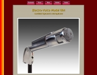 Electro-Voice Model 664 (EV 664) cardioid microphone, wiring diagram, pictures and data sheet
 -
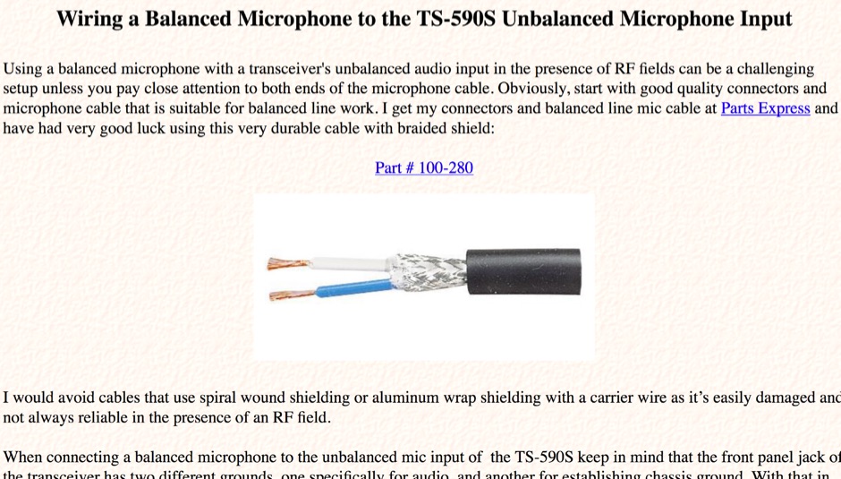 Wiring a Balanced Microphone to the TS-590S Unbalanced Microphone Input
 -
 Operating the _Icom IC-746_ HF/VHF transceiver often presents specific technical questions, and this resource compiles a comprehensive Frequently Asked Questions (FAQ) document in an ASCII text format. It details common inquiries and solutions related to the rig's functionality, accessories, and potential modifications. The content is structured into distinct sections addressing general information, power supplies, antennas, microphones, keyers, amplifiers, TNC integration, and optional IF filters. The FAQ provides practical guidance on topics such as configuring the internal automatic antenna tuning unit (ATU), selecting appropriate power supplies, and understanding microphone pin-outs. It also delves into advanced subjects like computer control via CI-V, wiring for PSK31 operation, and troubleshooting common issues like low S-meter readings on 2m FM or loose tuning shafts. Specific questions cover the installation of optional IF filters, comparing Inrad versus Icom filters, and optimizing filter combinations for various modes. Furthermore, the document outlines various hardware and firmware modifications, including those for increasing monitor volume, replacing LCD driver transistors, and implementing a "poor man's TCXO." It even touches upon untested modifications, such as replacing PIN diodes in the demodulator. The FAQ also lists manual errata and discrepancies, offering a robust knowledge base for IC-746 owners seeking to optimize their station or resolve operational challenges.
 -
 This online project guide details the construction of a homebrew boom microphone system. It details the assembly of a microphone shell from a 3/4" PVC pipe section and an end cap, requiring a drilled hole for a snug fit of the electret or condenser mic element. The internal wiring schematic specifies a **2.2 K** resistor and a **47 uF** polar capacitor for signal conditioning, with a circuit diagram provided for integration with IC-706 series transceivers. The guide outlines the use of CAT-5 cable for internal connections, incorporating strain relief at the rear of the mic shell, and an inline 3.5 mm jack to facilitate an external _PTT_ line, designed for a foot-mounted switch. Further construction involves fabricating a microphone shock mount from a 2-inch PVC connector, detailing the creation of four "fingers" and the insertion of screw-eyes for attaching elastic bands, which are twisted 180 degrees for tensioning and vibration isolation. A foam wind screen is also incorporated into the microphone assembly, secured with adhesive. The boom arm itself is repurposed from an articulated architect lamp, with the original lamp assembly converted into a **60 watt** resistive load for testing power sources. Microphone cabling is secured to the boom arm using wire ties, ensuring sufficient slack at hinge points to maintain articulation. The boom base is mounted to a bookshelf, requiring specific positioning to achieve proper microphone placement in front of the operator. Performance evaluation of the microphone system is conducted through on-air audio signal reports from other amateur radio operators. DXZone Focus: Online Project Guide | Boom Microphone Construction | Electret Mic Element | PTT Line
 -
 Constructing a digital interface for the Elecraft K2 transceiver, this resource details the "Fat Wire" design by WG4S. It demonstrates how to integrate a sound card for digital modes, outlining specific connections to the K2's microphone jack and internal audio path. The author shares practical insights from his build, including the use of _RG-62_ coax for its flexible braid and the strategic placement of components like the 2.2K resistor and _2N2222_ transistor. The guide provides a breakdown of the interface's internal wiring, specifying connections for AF In (pin 1), AF Out (pin 5), PTT (pin 2), and Ground (pin 7) on the K2's microphone connector. It also covers the external connections to a laptop's headphone and line-in jacks, along with a DB-9 connector for PTT control via _DTR_ or RTS lines. The author notes that his laptop's headphone output level was sufficient for the K2, negating the need for an attenuator. Reflecting on the design, the author, Dan WG4S, acknowledges a later suggestion to house the components directly within the DB-9 shell for a more compact build. This iterative feedback highlights the ongoing evolution of DIY ham radio projects and the community's collaborative spirit in refining designs.
 -
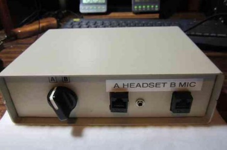 A 15-pin data switch, typically a rotary-knob type designed for DB-25 connectors, forms the basis for this microphone selector project. The resource details the conversion process, which involves replacing the original DB-25 connectors with **RJ-45** or **RJ-12** jacks to accommodate modern amateur radio microphones. It specifically addresses wiring for radios like the Icom IC-706 series (including the IC-7000 and IC-703) and Yaesu transceivers such as the FT-857, FT-897, FT-817, FT-7800, FT-7900, FT-8800, FT-8900, FTM-100, and FTM-400. The design ensures all microphone lines are switched straight through, with separate contacts for external speaker/headphone jacks, allowing simultaneous switching. The project emphasizes the practical application of switching between a headset for net control and a hand mic for rag-chewing without repeatedly plugging and unplugging cables. It highlights modifications to the original concept, such as eliminating a separate PTT jack by integrating PTT into headset cables and building the external speaker cable directly into the selector. The article provides guidance on managing the non-color-coded wiring often found in these data switches by soldering wires one by one from old to new connectors, ensuring correct pin alignment. This approach simplifies the conversion, making it accessible for hams seeking a functional and cost-effective mic switching solution.
 -
 Complete microphone wiring handbook for most popular radio transceivers provided by Astatic Microphones.
 -
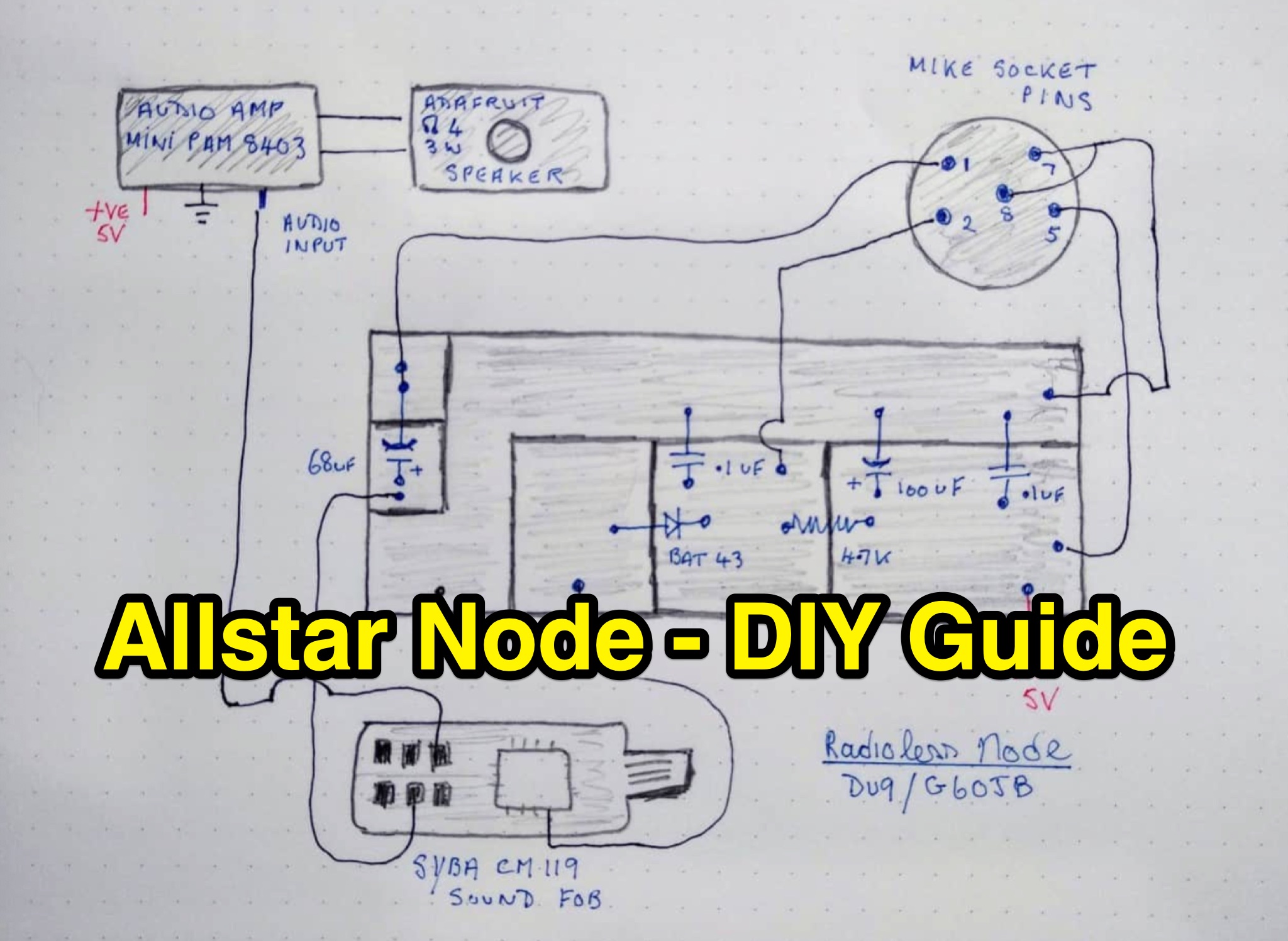 This page provides a detailed guide on how to build your own radioless Allstar node for ham radio operators. It includes information on power supply, components needed, wiring instructions, and tips to avoid common issues like ground loop hums. The author shares personal experiences and recommendations for specific components like microphones, audio amps, and sound fobs. Whether you're a beginner or experienced ham radio operator, this DIY project can help you set up a cost-effective and functional Allstar node for communication purposes.
 -
 This online project documentation details the construction of a hands-free microphone interface unit designed for _mobile_ amateur radio operation. The curriculum covers the integration of electret microphone elements with amateur radio transceivers, specifically addressing **VHF** band communication. It outlines the circuitry for a switch box that provides an interface between various radio models and microphone types. The guide specifies the inclusion of a **1750 Hz** tone-burst generator for accessing amateur radio repeaters, an operational protocol for many VHF systems. Design considerations include the reduction of ambient vehicle noise through an adjustable audio input level control. The project provides schematics and wiring diagrams for connecting the interface unit to specific amateur radio transceivers, including the Yaesu FT-817. It addresses the selection and adaptation of readily available electret microphone and earpiece assemblies, initially sourced from mobile phone accessories, and later from dedicated headset units. The design incorporates a control mechanism for radio functions, enabling hands-free operation during _mobile_ excursions. Circuit details cover power supply considerations for the electret microphone and signal routing for both transmit audio and received audio monitoring. The documentation specifies component selection for the switch box, ensuring compatibility with common amateur radio microphone input impedances and output levels. This includes considerations for PTT line switching and audio path isolation. DXZone Focus: Online Project Documentation | Hands-Free Mobile Microphone Interface | Electret Microphone Integration | 1750 Hz Tone-Burst Generation