Search results
Query: terminated loop
Links: 5 | Categories: 0
-
 Elongated Terminated Loops, usage and details by K9AY Lewallen
-
 The TMB-1 is an RF amplifier unit / receiving accessory that can be used with a low-impedance broadband loop, a high-impedance terminated loop (such as a Pennant, Flag, or Kaz Delta), and whip (telescoping rod) antennas.
-
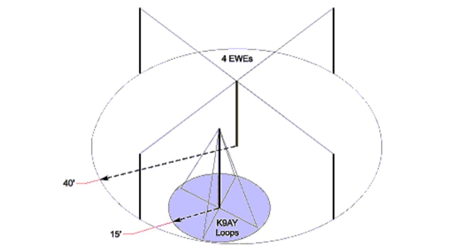 Presents the K9AY Loop, a compact, directional receiving antenna system optimized for low-band operation, demonstrating its design and construction. The resource details the physical and electrical simplicity of the terminated loop, which consists of a wire loop, a ground rod, a 9:1 impedance-matching transformer, and a terminating resistor. It compares the K9AY system's real estate requirements to an equivalent EWE array, showing it needs only one-seventh the area while providing identical directional patterns. The article includes schematics for the relay box and control unit, specifying components like DPDT relays, steering diodes, and a 43 material toroid for the matching transformer. The resource provides practical construction steps, including material lists for two 85-foot wire loops, insulators, a copper ground rod, and a 25-foot support. It discusses the critical role of the terminating resistor (RTERM), with values ranging from 390 to 560 ohms for 160m and 80m optimization, respectively. Performance evaluation methods are outlined, suggesting listening tests with local AM stations or WWV to verify front-to-back (F/B) ratios of 2 to 3 S units. EZNEC modeling results for vertical and horizontal radiation patterns are presented, showing a broad front lobe and a deep rearward null at 30-40 degrees elevation, crucial for reducing local noise and QRM.
-
 It is very compact, low noise and directive with an impressive 20 to 25 dB front to back
-
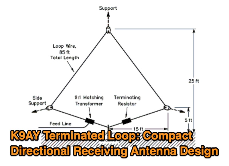 This resource presents the design and characteristics of the K9AY Terminated Loop, a compact directional receiving antenna system. The document details the antenna's physical and electrical configuration, consisting of a wire loop, a 9:1 impedance-matching transformer, and a terminating resistor. It describes how the antenna achieves directionality, favoring signals from the feed point end and rejecting signals from the terminating resistor end by several S units. The system is designed for low-band operation, specifically mentioning its application for improving reception on bands where space is a constraint. A four-direction system, utilizing two loops oriented at right angles with a relay-controlled switching system, is discussed. The resource includes a comparison of the K9AY loop's footprint to that of an equivalent EWE array, indicating the K9AY system requires approximately 1/7 the area while maintaining similar directional patterns. The design prioritizes signal collection sufficient for use with modest preamps, such as those integrated into HF transceivers. The article was originally published in QST in 1997.