Search results
Query: trapped hf antenna
Links: 8 | Categories: 0
-
 A rotary trapped-dipole for 17 and 20 meters, as described by IZ7ATH, presents a practical solution for multi-band HF operation. The author, Talino, recounts his experience building this antenna for IK7ZCQ, detailing the evolution from an initial concept involving a grounded-driven element and gamma-match to a direct-fed, non-grounded design. His pragmatic approach, adapting available materials, is evident throughout the construction narrative, particularly with the use of eight tapered aluminum pipes for the driven element. Construction specifics include precise measurements for the aluminum tubing, with diameters ranging from 30 mm down to 16 mm, and a critical note on reducing tip thickness for weight optimization. The _traps_, initially a concern, are fabricated using 8 turns of RG58 coax on a 27 mm support, tuned to resonate at 18.1 MHz using a dip-meter. Talino emphasizes sealing the traps with RF glue and PVC tape to prevent water ingress, a crucial step for longevity. Field test results, conducted on a 10-meter pole in a clear garden environment, showed an SWR of 1.2:1 on 17 meters and 1.5:1 at 14.200 MHz. While SWR varied slightly when installed at Mario's QTH due to nearby objects, the antenna's performance remained commendable. The final half-dipole length is 46 cm for the 18 MHz tips, and the total weight is under 6 kg, with potential for further reduction.
 -
 Video construction of a multiband HF trapped dipole antenna based on a variation of the classic W3DZZ design
 -
 The problem with making your own trapped HF antennas is usually getting the coaxial traps tuned to frequency.
 -
-
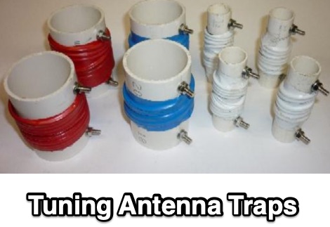 The problem with making your own trapped HF antennas is usually getting the coaxial traps tuned to frequency. This article explains a method using a RF signal generator at +10dBm output into the coaxial trap.
 -
 A Trapped dipole inverted V antenna for lower HF Bands. Construction details are for temporary installation. Permanent installations will require additional ruggedising and waterproofing however the basic electronics concepts remain the same. This project includes SWR plots for the three bands and pictures details of the homemade traps.
 -
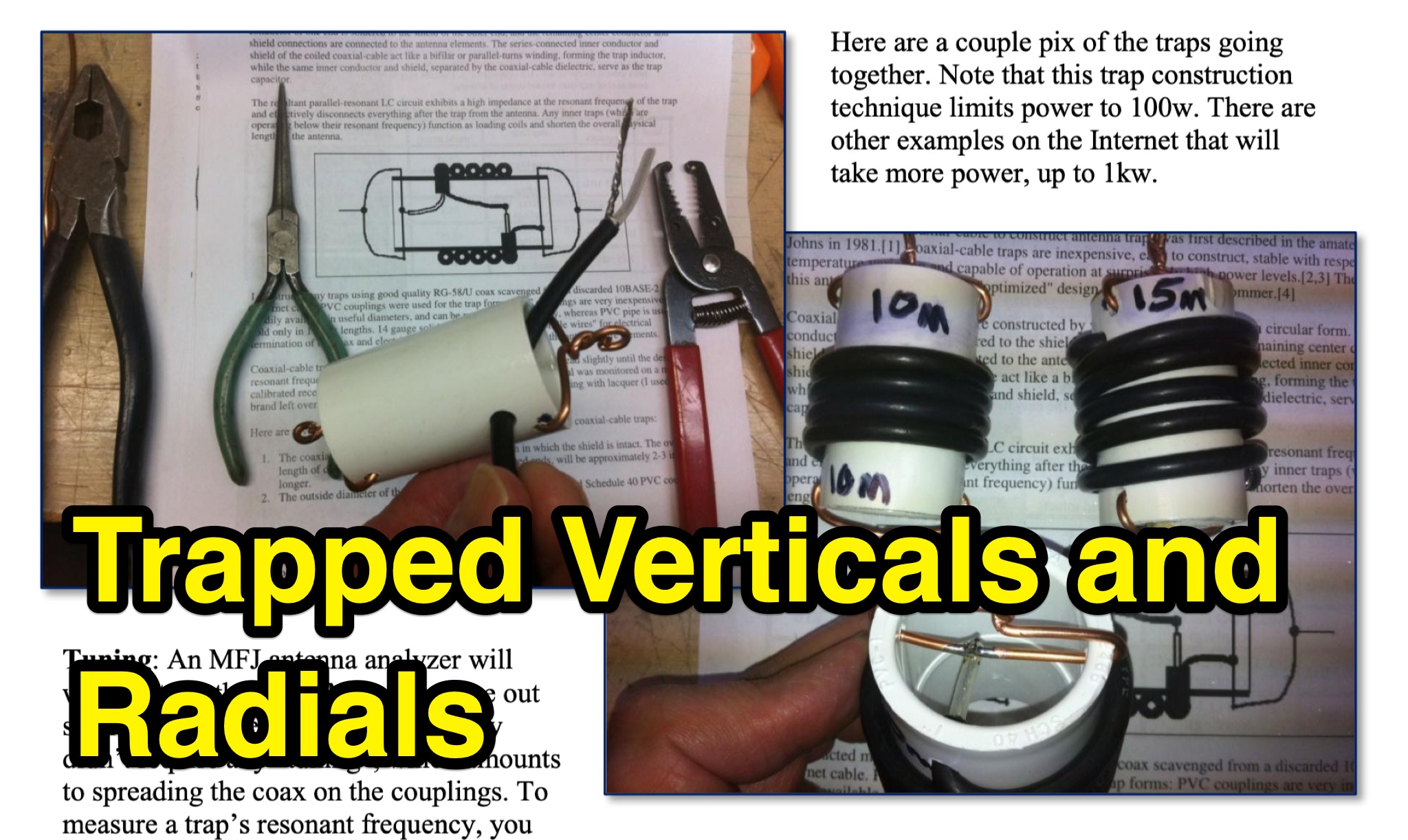 This PDF document provides detailed information on the design, construction, and tuning of trapped vertical antennas with radials for ham radio operators. It covers the theory behind trapped antennas, practical considerations for installation, and tips for optimizing performance. Whether you are a beginner looking to build your first HF antenna or an experienced operator seeking to improve your station setup, this guide offers valuable insights and instructions. By understanding the principles outlined in this document, hams can enhance their operating experience and make the most of their radio communication capabilities.
 -
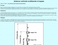
 The tri-band trapped delta loop antenna design operates on 80 meters (3.5–4 MHz), 40 meters (7–7.3 MHz), and 30 meters (10.1–10.15 MHz) using a single triangular wire loop. This configuration eliminates the need for an external antenna tuner or band-switching relays. The antenna's physical perimeter, approximately 270 feet, establishes 80M as the fundamental band, with specific trap placements enabling resonance on 40M and 30M. Trap design and placement are critical, with 30M traps positioned inboard of 40M traps within the horizontal element. Each slant leg measures approximately 80 feet. The resource references foundational information from the _ARRL Antenna Handbook_ and _ON4UN’s Low Band DXing_ regarding full-wave loop behavior and feedpoint impedances. The project aims to provide multi-band HF operation from a single, fixed antenna structure.