Search results
Query: 2-meter EME
Links: 54 | Categories: 0
-
 A 5/8-wavelength vertical antenna for 2-meter FM operation is detailed, focusing on eliminating loading coils by utilizing a series inductor to cancel capacitive reactance at the feed point, thereby presenting a 50-ohm impedance match. The design illustrates three basic configurations, including a method employing a short-circuited coaxial stub for inductance, as implemented by K4LPQ. An alternative design is presented where the center conductor of the stub is extended one-quarter wavelength, creating a signal-frequency short and allowing for an insulated wire stub to develop the required series inductance. The article provides electrical theory and mechanical considerations for building the antenna, emphasizing the adjustment of stub length for proper impedance matching. This technical documentation is intended for amateur radio operators interested in homebrewing VHF antennas, offering practical insights into impedance matching techniques for vertical radiators.
 -
 Constructing a **J-Pole antenna** from 450 Ohm ladder line for 2-meter (144 MHz) and 70-centimeter (440 MHz) operation involves specific calculations and assembly steps. The design, based on an earlier KD6GLF concept using 300 Ohm twinlead, features a ¾ wavelength radiator and a ¼ wavelength matching stub, functioning as an end-fed half-wave antenna without requiring ground radials. It offers a gain of 2.4 dB over isotropic. The resource provides the formulas for determining the lengths of the ¾ wave radiator and ¼ wave stub, incorporating a velocity factor of 91% for 450 Ohm ladder line. For 146 MHz, the radiator measures 55 3/16 inches and the stub 18 3/8 inches. Construction details include cutting a 57¾-inch piece of ladder line, stripping 4 inches from one end, and attaching a 24-inch section of RG58 or RG8X coax with a 3-5 turn RF choke. SWR adjustment is achieved by sliding a shorting bar or by incrementally trimming the elements at a 1:3 ratio (stub to radiator). The goal is a 1:1.1 SWR at 146 MHz, which typically yields 1:1.2 at 446 MHz. The article also discusses power handling, noting that while 10-15 watts is fine, 50 watts may increase SWR to 1:2.1, and advises keeping the antenna away from other objects to prevent coupling and SWR degradation.
 -
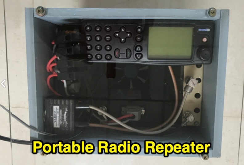 Demonstrates the construction of a portable 2-meter repeater system utilizing a **Yaesu DR-1X** transceiver, configured for both analog FM and C4FM digital voice operation. The design emphasizes portability, robustness, and effective thermal management, incorporating a "wind tunnel" airflow system with a fan to maintain transmit module temperatures at 38 degrees Celsius during continuous operation. The system integrates a diplexer, control head, and is housed in a compact, lightweight case weighing under 8kg, designed for single-person deployment. Covers practical considerations for field deployment, including power sources, antenna types, and the overall system architecture for public service events and emergency preparedness. The resource details the modular "wrap around" construction, showing how components like thermal switches for fan control and Anderson Powerpole connectors are integrated. It highlights the system's ability to provide reliable communications support for club activities and emergency communications.
 -
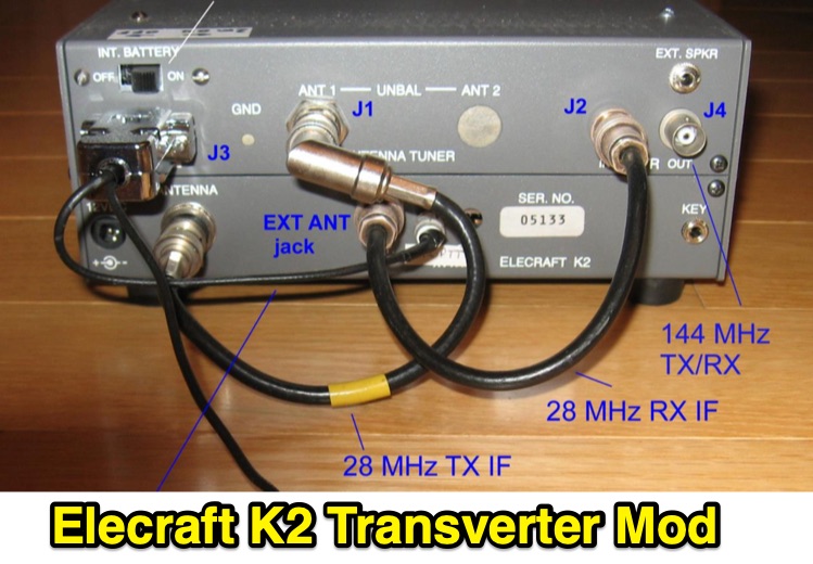 Demonstrates the conversion of an _Elecraft K2_ QRP HF transceiver to serve as a 2-meter Intermediate Frequency (IF) rig for microwave transverters, addressing the obsolescence of older _Yaesu FT-290R_ units. The project integrates a _DEMI 144-28DC_ transverter board, configured for a 28 MHz IF, and details the necessary modifications to the K2, including the installation of the K160M module for a separate receive-only antenna input and the KSB2 SSB module for voice operation. The modified K2 provides a stable 1-watt output for the 2m IF, utilizing the QRP antenna jack for transmit and the K160M input for receive, with a custom PTT control circuit. The article outlines the physical integration and electrical interfacing, including the design of an internal attenuator for the 28 MHz IF output and a control circuit for the 144 MHz interface. It also covers the construction of a medium power amplifier using an _MGA-31389 MMIC_ to boost the 2m output to 100 mW, matching the original FT-290R performance. Performance measurements for the amplifier, including output power versus input power and gain versus frequency, are presented. The project culminates in a fully integrated solution, with schematics and photos illustrating the internal wiring and external connectors. The modified K2, dubbed the "K290R," was successfully deployed in the 2017 _ARRL 10 GHz and Up Contest_ with a _Kuhne 10 GHz_ transverter, demonstrating reliable operation for CW and SSB modes.